CONTENTS
2 DESIGN STANDARDS AND CODES OF PRACTICE
2.1 Concentration Limit for Emission From Incinerators Municipal Waste Incineration
2.2 Calculation of Equivalent Concentration For Dioxins
APPENDICES
A Flow chart of Flue Gas Treatment System and the target air pollutants
B Relevant Parts of the Specification (Part C) and (Part D)
1 INTRODUCTION 1.1 Background
The Environmental Protection Department (EPD) Contract No. EP/SP/66/12, Integrated Waste Management Facilities (IWMF) Phase 1, was awarded to Keppel SeghersZhen Hua Joint Venture (KSZHJV) in November 2017 under a design-build-operate (DBO) arrangement. The IWMF comprises: (a) an advanced thermal incineration plant with operation capacity of 3,000 tonnes per day (tpd) and (b) a mechanical sorting and recycling plant with design capacity of 200 tpd. The non-recyclables sorted from the mechanical plant will be sent to the thermal incineration plant for further treatment. Under any conditions, the total MSW feeding to the thermal incineration plant will not exceed 3,000 tpd. The project will be located on an artificial island to the south of Shek Kwu Chau.
An environmental impact assessment (EIA) study for the Project have been conducted and the EIA Report was approved under the Environmental Impact Assessment Ordinance on 17 January 2012. An Environmental Permit (EP) (EP No.: EP-429/2012) was granted to EPD on 19 January 2012 for the construction and operation of the Project. Subsequently, the EP was amended (EP No.: EP-429/2012/A) and a further EP (FEP) (EP No.: FEP-01/429/2012/A) was granted to the KSZHJV on 27 December 2017.
Pursuant to Clause 2.7A of the FEP, a Flue Gas Emission Control Measures Implementation Plan shall be developed and deposited with the Director of Environmental Protection.
1.2 ObjectiveThe process and layout design of the Flue Gas Treatment System includes the following main equipment:
· Selective Non-Catalytic Reduction (SNCR) unit (built in the boiler first empty pass);
· First stage All-Dry system (operating at 240°C), with
- Sodium bicarbonate injection (NaHCO3);
- Filter bag system;
- Residue recirculation system;
· Selective Catalytic Reduction (SCR) unit (operating at ~ 235°C);
· External economiser unit (waterside integrated in the boiler circuit);
· Second stage All-Dry system (operating at 140°C), with
- Dry, hydrated lime injection (Ca(OH)2);
- Powdered activated carbon (PAC) injection;
- Filter bag system;
- Residue recirculation system;
· Induced Draught (ID) fan, with silencer;
· Stack with Continuous Emissions Monitoring System (CEMS);
The flowchart of Flue Gas Treatment System and the target air pollutants to be removed at each stage are summarized in Appendix A.
This Flue Gas Emission Control Measures Implementation Plan covers the following aspect:
(i) Design standards and codes of practice;
2 DESIGN STANDARDS AND CODES OF PRACTICEThe Flue Gas Treatment System shall comply with:
· The Industrial Emissions Directive 2010/75/EU of the European Parliament and of the Council of 24 November 2010 on industrial emissions (integrated pollution prevention and control), which replace the 2000/76/EC Incineration Directive
· The conditions of the Specified Process License and the Environmental Permit and the A Guidance Note on the Best Practicable Means for Incinerator (Municipal Waste Incineration) BPM12/1(08) published by EPD (all pollutant concentration limit values are expressed at reference conditions of 0°C temperature, 101.325 kPa pressure, dry and 11% oxygen content conditions).
· The Concentration Limits of NOx stated in Contract Specification were used for the design of flue gas emission control
· Permanent accessibility to equipment will be in line with the requirements of EN14122-Safety of machinery Permanent means of access to machinery.
· A Guidance Note on the Best Practicable Means for Incinerator (Municipal Waste Incineration) BPM12/1(08) published by EPD has been considered in the design
· Specification (Part C) Requirements for Process, Electrical and Mechanical Works (Clauses 2.1.4.1, 2.1.4.4, 2.4.11.34, 2.5, 2.6)
· Specification (Part D) Requirements for Operation and Maintenance (Clause 2.6.1.9) Relevant parts of the specification are attached in Appendix B.
2.1 Concentration Limit for Emission From Incinerators Municipal Waste IncinerationAir pollutant from the subject incineration process of this IWMF project shall not exceed the concentration limits tabulated in the following Tables 1 - 4. The air pollutant concentration is expressed at reference conditions of 0°C, 101.325kPa pressure, dry and 11% oxygen content conditions.
(a) Daily Average Value
|
Air Pollutant |
Concentration Limit (mg/m3) |
|
Particulates * |
10 |
|
Gaseous and vaporous organic substances, expressed as total organic carbon |
10 |
|
Hydrogen chloride (HCl) |
10 |
|
Hydrogen fluoride (HF) |
1 |
|
Sulphur dioxide (SO2) |
50 |
|
Nitrogen oxides, expressed as nitrogen dioxide (NO2) |
80 |
|
Carbon monoxide (CO) ** |
50 |
Table 1 Daily Average Value
(b) Half-hourly Average Value
|
Air Pollutant |
Concentration Limit (mg/m3) |
|
Particulates * |
30 |
|
Gaseous and vaporous organic substances, expressed as total organic carbon |
20 |
|
Hydrogen chloride (HCl) |
60 |
|
Hydrogen fluoride (HF) |
4 |
|
Sulphur dioxide (SO2) |
200 |
|
Nitrogen oxides, expressed as nitrogen dioxide (NO2) |
160 |
|
Carbon monoxide (CO) ** |
100 |
Table 2 Half-hourly Average Value
Note:
* Particulates shall monitor Respirable Suspended Particulates
** excluding the start-up and shut-down phases
(c) Average value over the sampling period of a minimum of 30 minutes and a maximum of 8 hours
|
Air Pollutant |
Limit Level (mg/m3) |
|
Cadmium and its compounds, expressed as cadmium (Cd) |
Total 0.05 |
|
Thallium and its compounds, expressed as thallium (Tl) |
|
|
Mercury and its compounds, expressed as mercury (Hg) |
0.05 |
|
Antimony and its compounds, expressed as antimony (Sb) |
Total 0.5 |
|
Arsenic and its compounds, expressed as arsenic (As) |
|
|
Lead and its compounds, expressed as lead (Pb) |
|
|
Chromium and its compounds, expressed as chromium (Cr) |
|
|
Cobalt and its compounds, expressed as cobalt (Co) |
|
|
Copper and its compounds, expressed as copper (Cu) |
|
|
Manganese and its compounds, expressed as manganese (Mn) |
|
|
Nickel and its compounds, expressed as nickel (Ni) |
|
|
Vanadium and its compounds, expressed as vanadium (V) |
Table 3 Average value over the sampling period of a minimum of 30 minutes and a maximum of 8 hours
(d) Average value over the sampling period of a minimum of 30 minutes and a maximum of 8 hours
|
Air Pollutant |
Limit Level (ng I-TEQ/m3) |
|
Polychlorinated dibenzodioxins and polychlorinated dibenzofurans (see Section 2.2 for the calculation of equivalent concentration) |
0.1 |
Table 4 Average value over the sampling period of a minimum of 30 minutes and a maximum of 8 hours
The concentration limits for NOx and ammonia (NH3) from flue gas emission as specified in paragraph 2.1.4.3 of the Specification (Part C). See below.
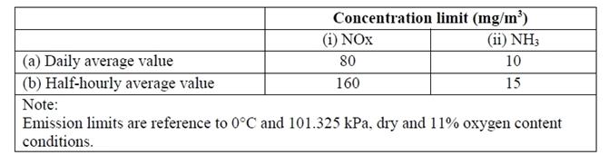
Table 5 Concentration Limits for NOx and Ammonia
2.2 Calculation of Equivalent Concentration For DioxinsFor the determination of total concentration of dioxins and furans, the mass concentrations of the following dibenzodioxins and dibenzofurans shall be multiplied by the following equivalence factors before summing:
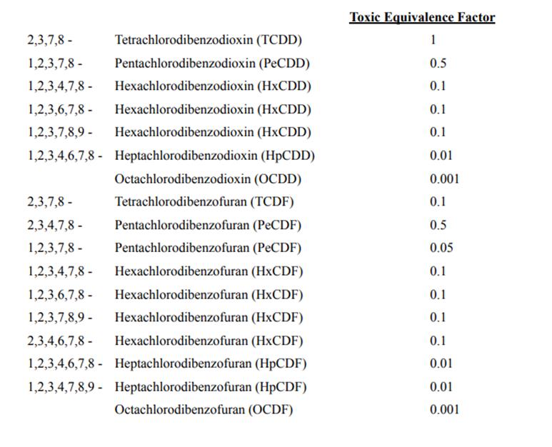
Table 6 Total Equivalence Factors