Revision History
|
F |
Response to EPD comments 5 Aug 2022 |
16 Nov 2022 |
|
E |
Response to EPD comments 24 Feb 2021 |
4 Jul 2022 |
|
D |
Amended to include 3 tier container stacking impacts |
2 Nov 2020 |
|
C |
Response to EPD comments 27 Aug 2018 and 11 Sep 2018 |
3 Oct 2020 |
|
B |
Response to IEC’s comment on 24 May 2018 |
25 May 2018 |
|
A |
First Issue |
23 May 2018 |
|
Rev. |
Description of Modification |
Date |
CONTENTS
1.2 Scope of this Landscape and Visual Plan
2 LEGISLATION, STANDARDS AND GUIDLEINES
2.1 Government Technical Circulars, Publications, Guidelines and Reports
2.2 Ordinances and Regulations
4 DETAILED TREE PRESERVATION, TRANSPLANTING AND FELLING PROPOSALS, COMPENSATORY PLANTING PROPOSAL
4.1 Tree Preservation, Transplanting and Felling Proposals
4.2 Master Landscape Layout Plan
5 LANDSCAPE WORKS TO BE CONSTRUCTED UNDER THIS PROJECT
5.1 Landscape Design Considerations
5.2 Landscape Area at Grade Level (See Annex B)
5.5 Soft Landscape (See Annex B, Figures 5.1 and 5.2)
5.6 Vertical Greening (See Annex B and Figures 6.2 and 6.3 )
6 AESTHETIC DESIGN OF THE BUILDING STRUCTURES, CHIMNEY AND BREAKWATER
6.2 Subtle Variegation in Colours of the Façades to Rhyme with Nature
6.3 Variety in Form of the Façade to Rhyme with Nature
6.4 Vertical Greening to be an Integral Part of the Architecture
6.6 Avoidance of Industrial Impression in Chimney Design
6.7 Aesthetic design of breakwater
6.8 Aesthetic design building structures
6.8.2 Materials Treatment Building and Water Treatment Plant Building
6.8.4 Turbine Hall, ACC and CCCW
6.8.5 IWMF Substation Building
7 LANDSCAPE AND VISUAL IMPACT AND MITIGATION MEASURES
7.1 Landscape and Visual Design Measures in EIA & EM&A
7.4 Maintenance and Management Schedule
7.5 Maintenance Responsibilities for Landscape Works
APPENDICES
Annex A
Annex A
Part 2 Updated Photomontages presenting the updated Visual Impacts
Annex B Preliminary Landscape Masterplan & Landscape Design for Water Feature including Design Drawings
Annex C Seawall and Breakwater Details
Annex D Comments and Responses
1 INTRODUCTION 1.1 BackgroundThe Environmental Protection Department (EPD) Contract No. EP/SP/66/12, “Integrated Waste Management Facilities (IWMF) Phase 1”, was awarded to Keppel Seghers–Zhen Hua Joint Venture (the JV) in November 2017 under a design-build-operate (DBO) arrangement. The IWMF comprises: (a) an advanced thermal incineration plant with design capacity of 3,000 tonnes per day (tpd) and (b) a mechanical sorting and recycling plant with design capacity of 200 tpd. The non-recyclables sorted from the mechanical plant will be sent to the thermal incineration plant for further treatment. Under any conditions, the total MSW feeding to the thermal incineration plant and the mechanical plant will not exceed 3,000 tpd. The project will be located on an artificial island to the south of Shek Kwu Chau (SKC) as shown in Figure 1-1.
Arcadis Design & Engineering Limited (Arcadis) including their sister company ACLA were engaged by the JV as their designer to undertake the design of the civil, structural, geotechnical, MEP, landscape architecture and marine works. Subconsultant to Arcadis, DLN Architects (DLN) have been engaged to undertake architectural design, while subconsultant Adrian L. Norman Limited (ALN) has also been engaged to undertake the detailed landscape architectural design.
A full list of Figures is included at the back of the Report, with the some of the rendering figures being “Artist’s Impressions” as the design are being continually developed and refined.
![]()
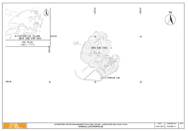
Figure 1.1 Overall Site Configuration / Layout
1.2 Scope of this Landscape and Visual PlanThis Landscape and Visual Plan is prepared in accordance with Clause 2.11 of EP No. FEP-01/429/2012/A. The Landscape and Visual Plan for the entire Project is required to address the following aspects: -
(i) aesthetic architectural designs for building structures, chimney and breakwater;
(ii) locations, size, number and plant species of trees to be transplanted and their final transplanting locations;
(iii) locations, size, number and plant species to be felled;
(iv) locations, size, number and plant species to be provided or compensated; and
(v) implementation programme, maintenance and management schedules.
The site is currently un-reclaimed foreshore adjacent to Shek Kwu Chau. No existing landscaping plant species will therefore be affected by the works associated with the IWMF Phase 1 development.
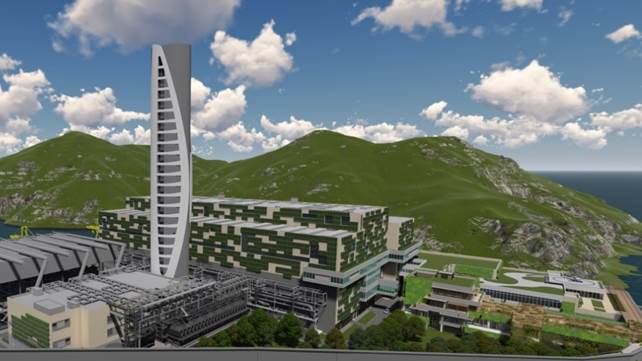
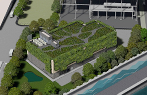
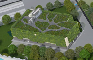
This report also presents the landscaping design concept for the development. This Plan will be developed further during the ongoing detailed design of the Project and may subject to further changes or variations as requested by EPD. A general overview of the site is presented below in Figures 1.2 and 1.3. Full details of the proposed Landscape Masterplan are included in Annex B. The landscape masterplan includes a full description of the proposed landscaping features including large scale drawings (Nominally not less than 1:1000 and mainly 1:200 for the whole site.)
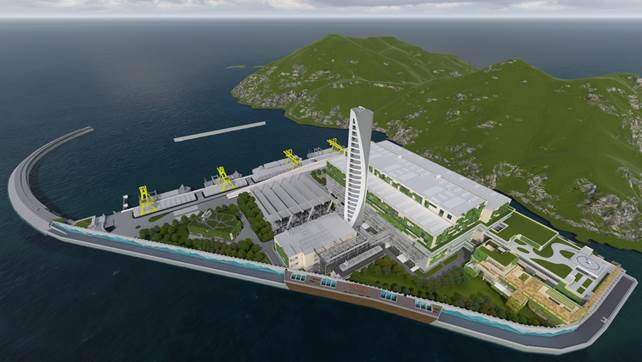
Figure 1.2 General overview of the IWMF development and adjacent Shek Kwu Chau Island from the South.
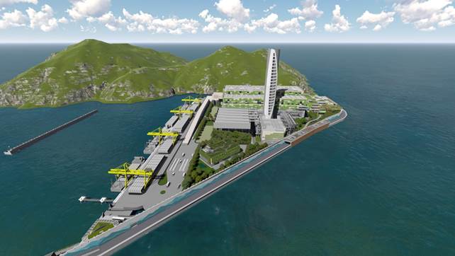
Figure 1.3 General overview of the IWMF development and adjacent Shek Kwu Chau Island from the West.
1.3 Abbreviations
|
Government Bureaux, Departments and Related Organisations / Authorities |
|
|
EPD |
Environmental Protection Department |
|
|
|
|
Locations / Places |
|
|
IWMF |
Integrated Waste Management Facilities |
|
SKC |
Shek Kwu Chau |
|
|
|
|
Others |
|
|
DBO |
Design-build-operate |
|
EIA EM&A |
Environmental Impact Assessment Environmental Monitoring and Audit |
|
FEP LCA |
Further Environmental Permit Landscape Character Area |
|
LR |
Landscape Resource |
|
MT |
Mechanical Treatment |
|
VSR WTP |
Visual Sensitive Receiver Water Treatment Plant |
2 LEGISLATION, STANDARDS AND GUIDLEINES 2.1 Government Technical Circulars, Publications, Guidelines and Reports
Government Technical Circulars, Publications, Guidelines and Reports related to Landscape Design include:-
· Practice Notes for Authorized Persons and Registered Structural Engineers and Registered Geotechnical Engineers, APP-152: Sustainable Building Design Guidelines
· Protection of natural streams/rivers from adverse impacts arising from construction works (PNAP No. 295)
· GEO Publication No. 1/2011: Technical Guidelines on Landscape Treatment for Slopes
· ETWB TCW No. 13/2003: Guidelines and Procedures for Environmental Impact Assessment of Government Projects and Proposals
· DEVB TC(W) No. 5/2017: Community Involvement in Planting Works
· DEVB TC(W) No. 6/2015: Maintenance of Vegetation and Hard Landscape Features
· DEVB TC(W) No. 5/2020: Registration and Preservation of Old and Valuable Trees
· ETWB TCW No. 36/2004 The Advisory Committee on the Appearance of Bridges and Associated Structures (ACABAS)
· DEVB TC(W) No. 02/2012 Allocation of Space for Quality Greening on Roads
· DEVB TC(W) No. 03/2012 Site Coverage of Greenery for Government Building Projects
· DEVB TC(W) No. 02/2013 Greening on Footbridges and Flyovers
· DEVB TC(W) No. 4/2020 Tree Preservation
· Technical Memorandum on Environmental Impact Assessment Process (EIA Ordinance, Chapter 499, section 19) 1st ed, September 1997
· EIAO Guidance Note Nos. 1/2010, 3/2010, 5/2010 and 8/2010
· A Guide to the Environmental Impact Assessment Ordinance, 1999
2.2 Ordinances and Regulations
Ordinances and Regulations related to Tree Survey and Tree Risk Assessment include:
· Forests and Countryside Ordinance (Cap. 96) and its subsidiary legislations
· Plant Varieties Protection Ordinance (Cap. 490)
· Protection of Endangered Species of Animals and Plants Ordinance (Cap. 586)
3 BASELINE REVIEWA baseline review has been undertaken prior to the commencement of the construction works, the purpose of the baseline review is as follows:-
· To check the status and any changes to the baseline Landscape Resources, Landscape Character areas and Visually Sensitive Receivers (VSRs) within and immediately adjacent to the works areas;
· To determine whether amendments to the design of the landscape and visual mitigation measures will be required; and
· To recommend any necessary amendments to the design of the landscape and visual mitigation measures due to the above changes, if any.
The baseline review survey was conducted between February and April 2018. The review survey was directed towards assessing the Landscape Resources, Landscape Character Area and the impact on Visually Sensitive Receivers (VSRs) as identified in the EIA Report. The current condition of the site, the VSRs and their outlook and current conditions have been identified and are presented in photographs as attached in Annex A Part 1. The views presented correspond to those views applicable to the VSRs and are as presented in the approved EIA.
Photomontages depicting the proposed changes to the views from the VSRs are presented in Annex A Part 2.
In general, a comparison of the current conditions as presented in photographs included in Annex A Part 1 of the assessment and the updated proposed changes as presented in the photomontages included in Annex A Part 2 can be undertaken. It can be concluded that no significant changes will be observed from any of the VSRs. It is important to note that the site is remote and the VSRs identified in the EIA are located at some distance from the site. It can therefore be concluded that the visual impact of the site and its landscaping will have only a distant and therefore very small impact on the visual outlook from the VSRs.
4 DETAILED TREE PRESERVATION, TRANSPLANTING AND FELLING PROPOSALS, COMPENSATORY PLANTING PROPOSAL 4.1 Tree Preservation, Transplanting and Felling ProposalsThe reclamation area to be occupied by the IWMF Phase 1 development is isolated from SKC island. The site is currently un-reclaimed and no part of the IWMF site extends above low tide level at the present time. There will therefore be no direct impact on existing trees. As a consequence of the marine nature of the site no Tree Preservation, Transplanting and Felling Proposal will be required. Similarly, no Old and Valuable Trees will be affected by the proposed development, the site currently being covered by the sea.
The project land allocation includes a series of offsite short term works areas for use by the JV during the construction works phase. It is confirmed that these areas have already been cleared of trees under previous allocation for other projects. At the time of handover of these parcels of land it can be confirmed that no tree felling or transplanting of trees will be required.
4.2 Master Landscape Layout Plan
The proposed landscaping for the site is presented in the master landscape layout plan and a series of large-scale detailed landscaping plans as presented in Annex B. The location, size, number and plant species to be provided as part of the landscaping works are illustrated and described in the master landscape layout plan as included in Annex B.
5 LANDSCAPE WORKS TO BE CONSTRUCTED UNDER THIS PROJECT 5.1 Landscape Design Considerations
The landscaping developed for the IWMF will address the following concerns in terms of the landscape design:
1 The need for effective pedestrian and vehicle circulation within the development.
2 Security of the site should form an integral part of the design in terms of access control and ensuring visibility of the at grade areas.
3 Landscaped areas at grade and on upper levels should be accessible and safe for public and staff to promote a comfortable and welcoming environment.
4 Double structural slabs under planters will be considered where necessary to ensure no water leakage to the floors of buildings underneath.
5 The height of parapet walls and railings at roof levels will be carefully considered to avoid objects falling and to avoid adverse or potentially dominating visual effects.
6 Maintenance requirements should be kept to a practical minimum without compromising the operation of the facilities and their aesthetic design.
7 The choice of hard landscape materials (i.e. paving, pergolas, seating, etc.) should take into account sustainability, recyclability and durability.
8 Planting should be varied and stimulating, while endeavouring to be sustainable while not being unduly maintenance-intensive.
9 The landscaping should be designed to reduce the visual impact of the sea defence works and particularly the extensive seawalls and breakwater surrounding the site.
10 For a summary table of showing the approximate numbers of new trees, areas of shrubs, ground cover and vertical greening proposed, refer to Table 5. Below.
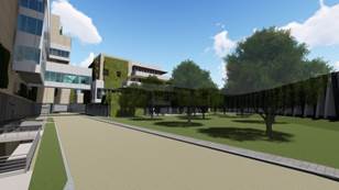
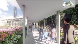
5.2 Landscape Area at Grade Level (See Annex B)The site will be divided into a discrete Visitor Zone and an Operation Zone. The Visitor Zone will be located along the southwestern side of the site and will follow a parallel route along the shoreline to enhance the visual impact of the tall seawalls. The Operation Zone will be located towards the northern part of the island and will remain out of bounds but visible for visitors for reasons of operational security and safety. A “Dense Forest Journey” has been selected as the theme for the Visitor Zone, aiming to provide a rich green environment for visitors and to improve the microclimate of the island. The theme has been selected to mitigate the visual impact associated with the sea defences which have necessarily been robustly designed to ensure the security of the facility from potentially severe wave action and flooding during typhoon events.
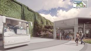
The Visitors’ Journey will start from the Passenger Ferry Pier and the associated Reception Pavilion located at the northwestern corner of the shoreline. Following security clearance visitors will be directed to a shuttle bus which will travel along a dedicated visitor vehicle access route along the sea wall towards the east. Visitors will enjoy the sea view from the shuttle bus, with a textured and sympathetically coloured wave themed mural along the landward side of the road, including a welcoming reception at the Administration Building with an adjacent water feature located close to the arrival as the bus turns the corner to the Administration Building. The Administration Building will include reception facilities at ground floor level and educational facilities as part of a Visitor Experience, including presentation spaces and views from galleries into the waste management processes at the operational floors within the Administration Building. The design has been developed to enhance the sense of arrival before entering the Viewing Gallery and presentation/ educational spaces within the Administration Building.
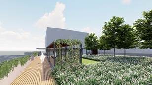
After finishing their visit, visitors can either return to the visitor pavilion by the shuttle bus or alternatively take a short gently descending walk across the pedestrian linkage from the 2/F of Administration Building roof garden. This arrangement will provide a chance for visitors to enjoy the outdoor environment. A Skybridge will start from the roof garden and will pass over/through the ”Dense Forested and Landscaped Area” along a “Tree Top Walk”, which will include a “Viewing Platform” to enjoy the panoramic sea view contrasting with the plant buildings on the landward side of the path. A gentle slope down the sheltered side of the sea wall through the woodland pathway will provide a lush greened experience. A water feature towards the end of the journey will be used to demonstrate the effective reuse of treated water from the facility.
A row of tree planting with dense foliage has been introduced along the northeast edge of the development to screen the road and mitigate visual impact to VSRs from SKC island.
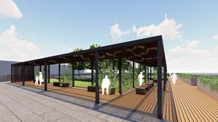
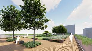
5.3 Landscape Areas Above Grade Level (See Drawing nos. IWMF1-LVP-01 and IWMF1_10-130_990_000250 in Annex B)Accessible green roofs within this project will be designed to act as an elevated park feature. This is intended for use by operations staff and visitors. This feature will act as a garden, with shrubs and small tree planting, pathways, seating and shade structures. Roofs will be selectively opened to visitors for security reasons and will be provided with irrigation, drainage and root protection layers to optimise the vegetative coverage.
The roof above the waste reception hall within the Main Process building will however be provided with comprehensive greening. The turbine hall, CCCW building and Air cooled condensers comprise plant and equipment enclosures. These structures will not be equipped with green roofs to avoid a conflict with the plant and equipment mounted on the roofs. Green roofs will be provided for all other building structures except in areas affected by the helicopter landing pad and road access. The helicopter landing pad has been located to comply with the specified flight path constraints and will be surrounded by lawn style green roof areas. The drawings have been annotated to identify the various building functions.
As a part of the visitor path, the roof garden of the Process Building will demonstrate the use of both treated water and harvested rainwater for irrigating the coastal plants which will be selected for their hardiness and suitability for the location. The display garden will be enhanced by exhibits and interactive features for educational purposes.
Various levels of roof garden at the Mechanical Treatment Plant Building will facilitate viewing along the gallery corridor. Tree planting will be restricted so as not to interfere with the emergency helicopter landing platform.
A Second Floor of the roof garden at the Administration Building will provide the connection with the Skybridge and the connection with the pedestrian link to the Ferry Pier.
5.4 Hard LandscapingThe landscape design within the visitor route will cater for visitors having different levels of mobility. Ramps and barrier free access design will be incorporated throughout the whole length of the visitor pathway. Sensory elements such as tactile, auditory, olfactory and visual enhancement to facilitate use by visitors with differing abilities and age groups. Specific consideration has been given to the whole spectrum of both visitors and operations staff in developing the landscape features.
Hard landscape materials selections will emphasise durability, ease of maintenance and sustainability (i.e. paving, pergola, seats, etc.). Adequate slip resistance (of R12 or equivalent) will be specified throughout to ensure users’ safety. Hard landscape materials have been chosen specifically for ease of maintenance and to be readily available in the local market. (See Annex B)
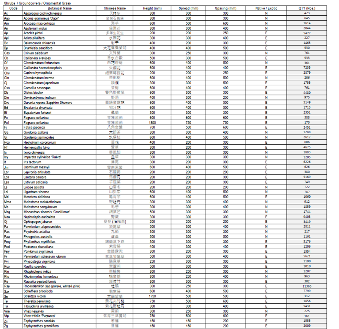
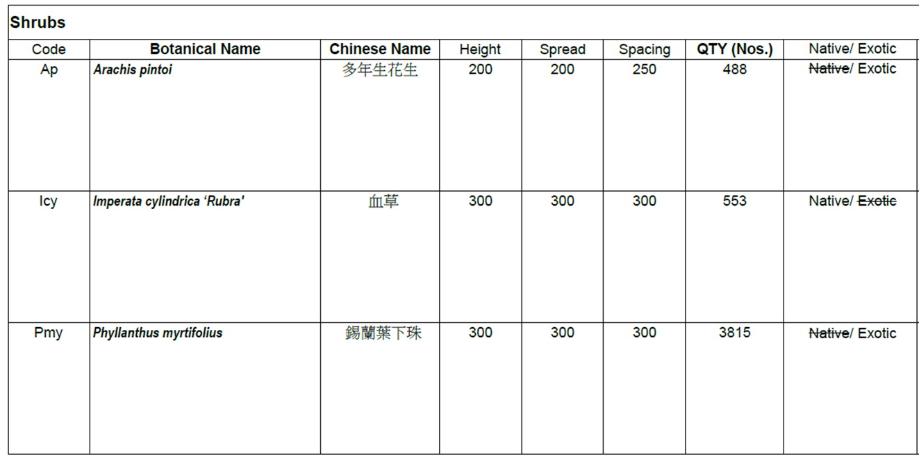
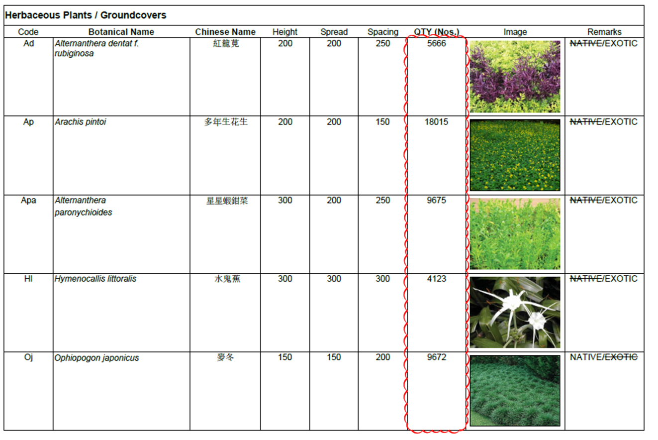
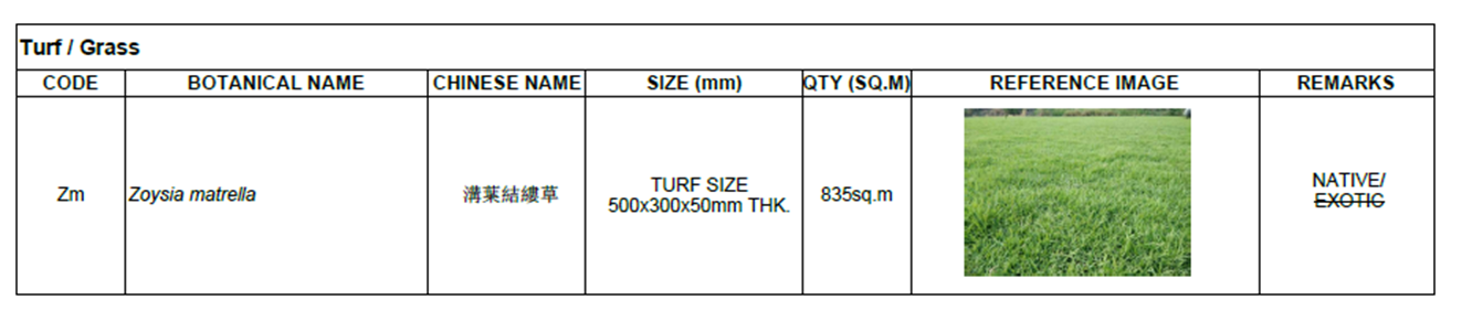
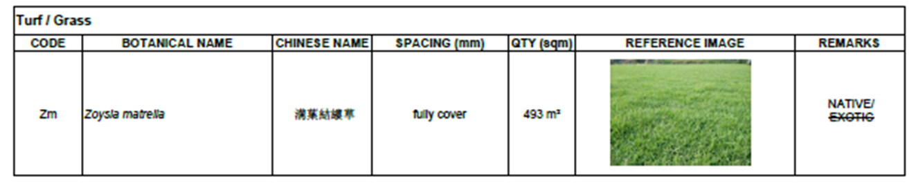
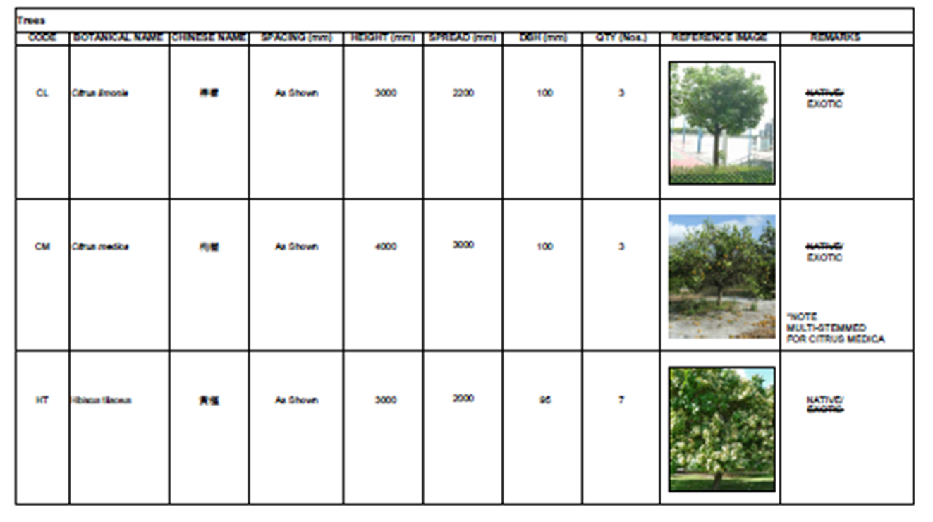
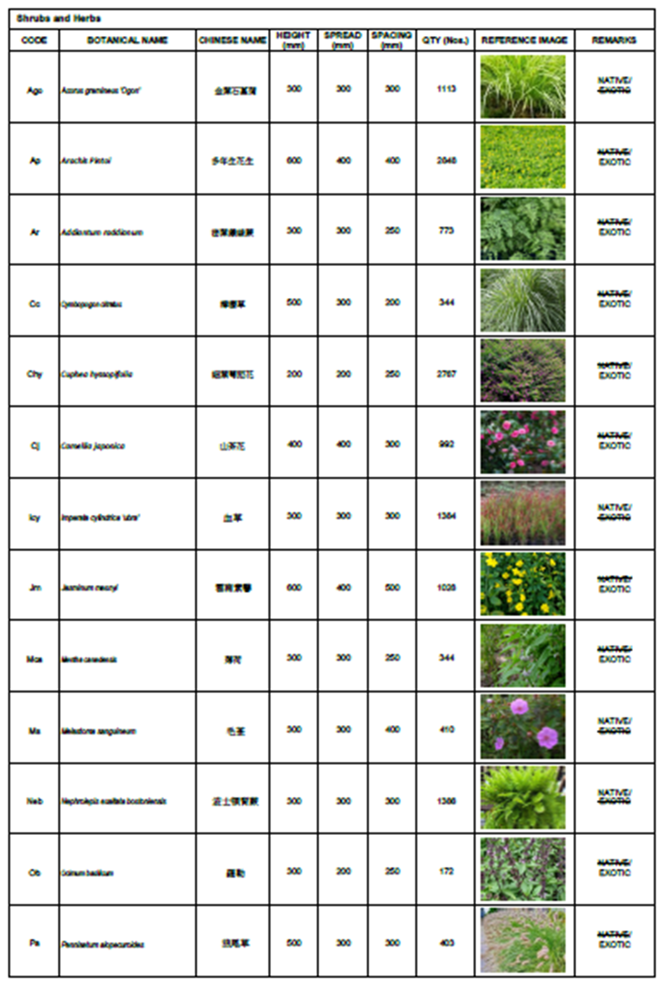
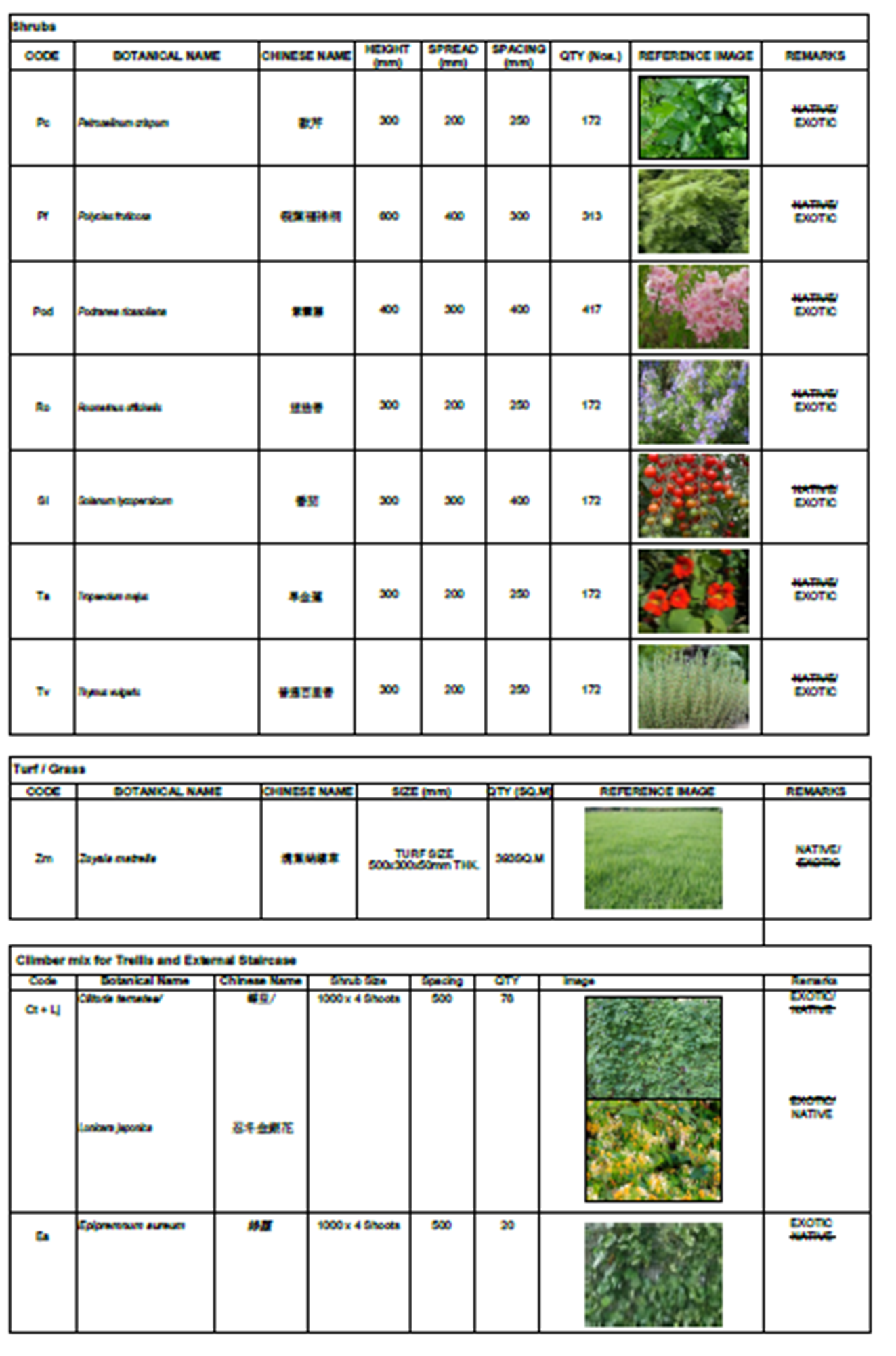
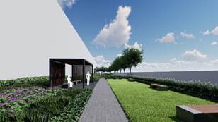
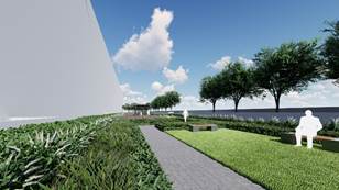
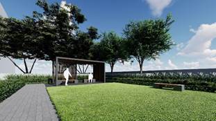
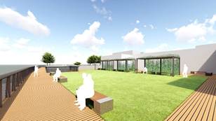
5.5 Soft Landscape (See Annex B, Figures 5.1 and 5.2)The design theme for the landscape is “Dense Forest”. The planting design has considered the special conditions associated with the coastal environment. Coastal buffer planting such as Syzygium jambos are proposed due to their high salinity tolerance and their ability to thrive in shoreline conditions.
The planting palette has been selected using grouping into 4 distinct and different planting zones, namely the Woodland Mass Planting, Coastal Green Buffer, Roof Garden Ornamental Planting and Leisure Gardens (see Drawing No. IWMF-LVP-02 in Annex B).
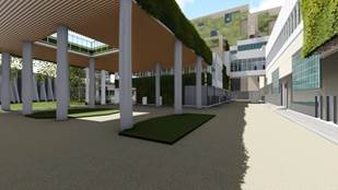
The main palette type will comprise Woodland Mass Planting, which will be a mixture of native tree species with high salinity tolerance that will be able to thrive in sea shore conditions. Native trees naturally fitting with the local environment will be selected to be supportive of the local ecology. Dense foliage of Woodland Mass Planting will also serve as a visual barrier to mitigate visual impacts, in particular along the southern and north-eastern periphery of the project site. Figures 5.1 and 5.2 showcase the East and West Courtyards whereby the design theme are illustrated.
Woodland Mass Planting (also known as “Dense Forest” in the AIP submission) is located within the on-grade large open spaces behind the seawall in the east and west courtyard areas. The planting of trees in this area is relatively more “dense” and “woodland” type trees provide a “forest-like” character compares with the remaining 3 planting zones.
The “Coastal Green Buffer” as the name implies are beside the coast and acts as “buffer” planting. This refers to the row of Hibiscus tiliaceus trees located along a northwest and southeast direction facing Shek Kwu Chau Island.
Roof Garden Ornamental Planting as the name implies are located within the “Roof” podium planters.
Leisure Gardens are located in the more open “less dense forest” area at-grade within the East and West Courtyard area (near the ponds).
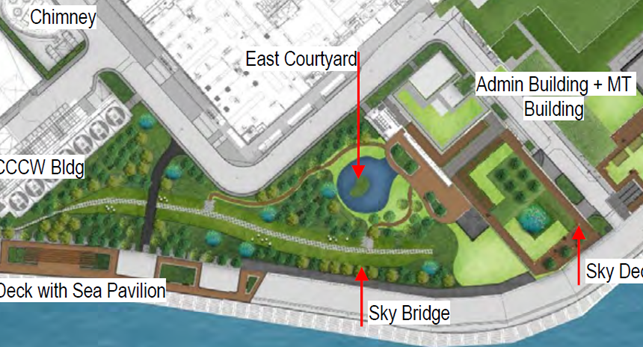
Figure 5.1 East Courtyard
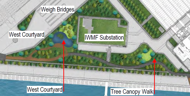
Figure 5.2 West Courtyard
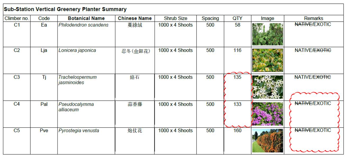
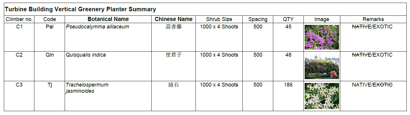
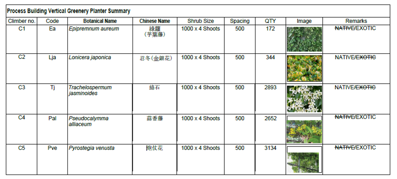
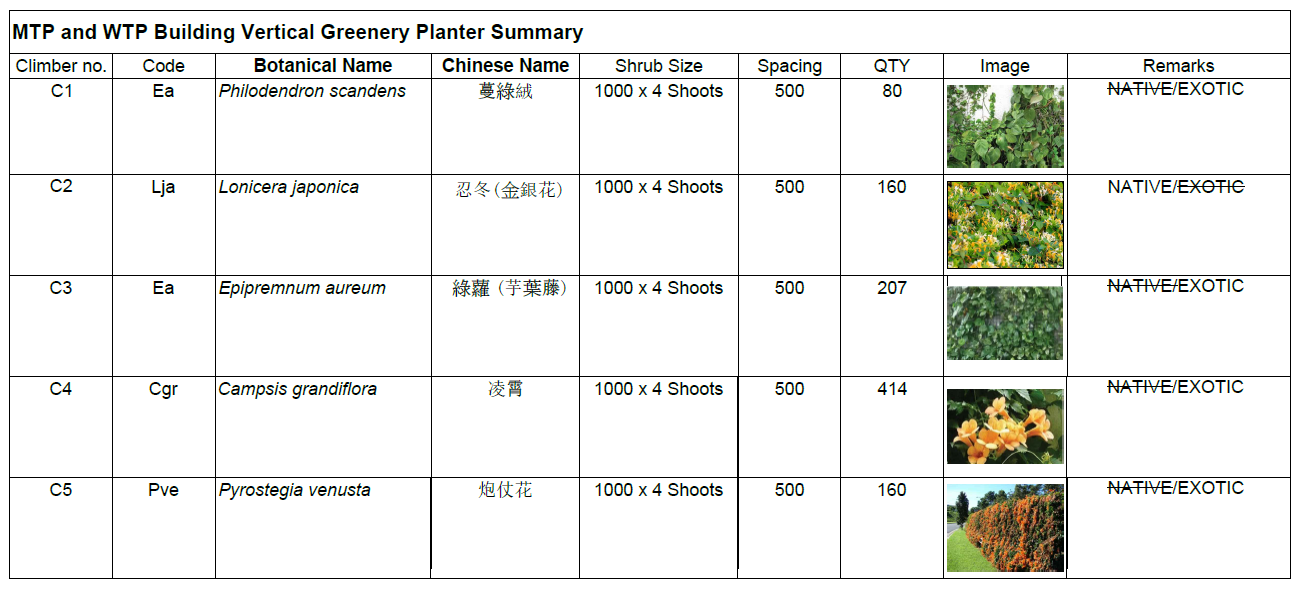
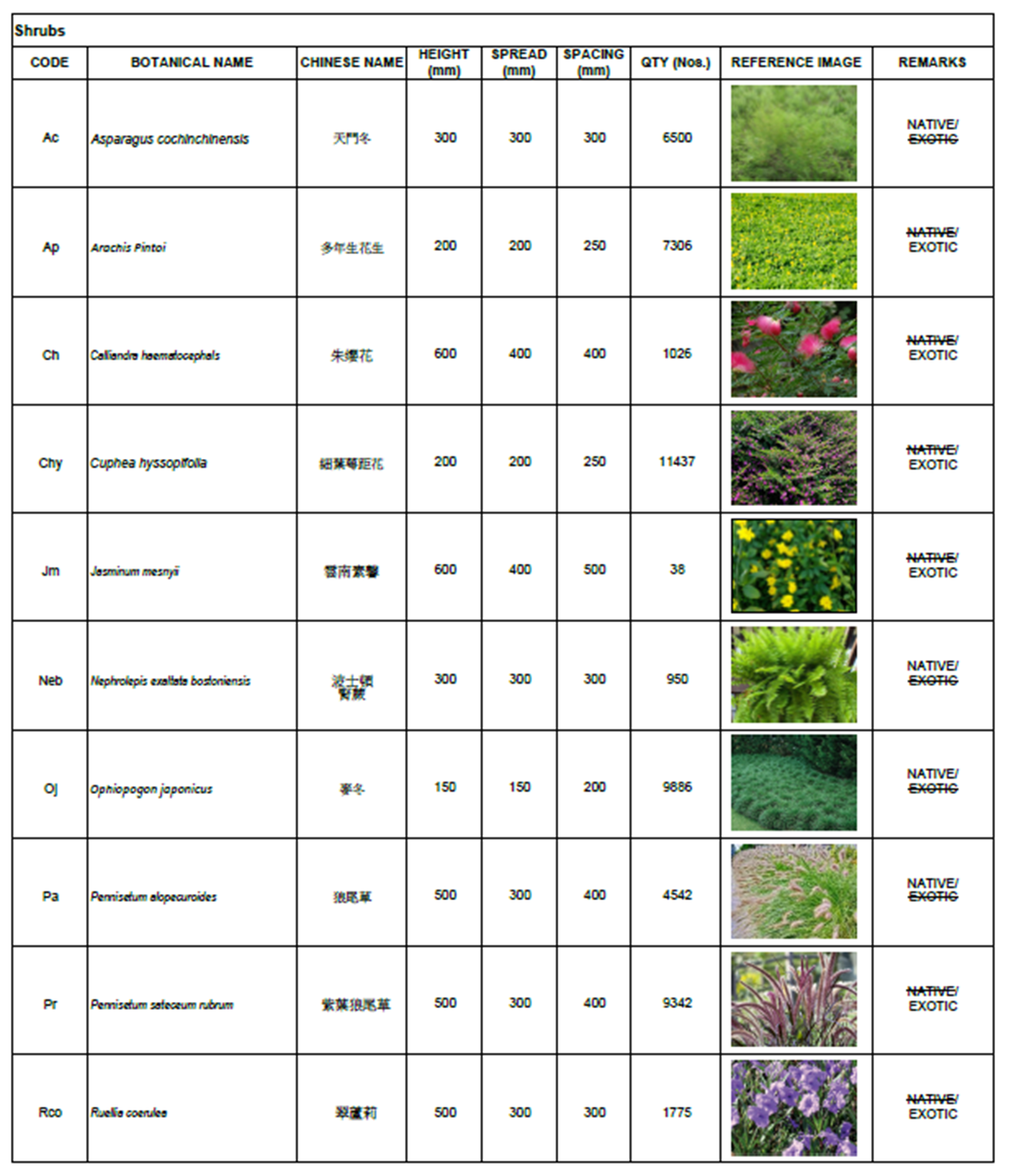
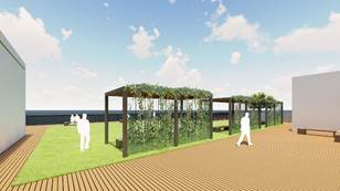
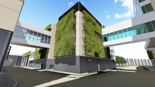
5.6 Vertical Greening (See Drawing nos. IWMF1_14-136_990_124101, IWMF1_14-136_990_124102, IWMF1_14-136_610_014201, IWMF1_14-136_500_114201, IWMF1_14-136_500_114202, IWMF1_14-136_500_114203, IWMF1_14-136_700_114201, IWMF1_14-136_700_114202, IWMF1_14-136_700_014203, IWMF1_14-136_300_114201 , IWMF1_14-136_300_114202 , IWMF1_14-136_300_114203, IWMF1_14-136_500_114201, IWMF1_14-136_800_114202, and IWMF1_14-136_800_114203 in Annex B )Vertical greening will be provided on the façades of the buildings and has been selected to maximize environmental and amenity values. The location of vertical greening will take into account façade orientation and the sun path especially for the wintertime to allow a variety of plant species choices and healthy growth of the vegetation.
The vertical greening system will integrate planter boxes into the building façade. These modular panels will be of standardized size and will provide an overall green and lush appearance for the whole site. Planting species with wind and salinity tolerance have been chosen for their low maintenance requirements.
5.7 Roof GreeningThe selected vegetated green roof systems have been selected to reduce storm water runoff, encourage lower cooling costs and to enhance the outlook of the project. Both inaccessible and accessible green roofs will be incorporated into this project.
Inaccessible green roofs will be accessible for periodic maintenance. These will have 0.3m planting soil allowing the growth of groundcover. Automatic irrigation systems will be provided for low maintenance and efficient watering. Inaccessible roofs will be located at the Reception Pavilion, IWMF Substation and the gallery walkway.
A green roof will not be incorporated in the Main Turbine Hall as the roof of the building will need to accommodate process related pipework and equipment. To ensure the effective air exchange, air cooled condensers building and turbine hall buildings will also not incorporate green roof designs.
Green roof is provided on top of the Bunker portion of the Process Building, rather than the whole of the Process Building. Careful considerations have been made by taking into account the various operational requirements to enable the efficiency and function of the IWMF. For instance, therein lies multiple ventilation openings, access openings, smoke outlets, etc. on top of the roof to provide a coherence and efficient roof greening system. These ventilation openings will also potentially affect the healthy growth of the surrounding vegetation by the high temperature that they induce during operation. Moreover, the contractual requirement that the waste crane within the building to have the ability to be removed (for operational/maintenance/replacement functions) would mean the roof has to be sufficiently functional and flexible to be dismantled, in order to facilitate the removal such a large piece of equipment. Nevertheless, it is noted that the overall site coverage of greenery meets the contractual requirement, including the roof greening.
For details of accessible green roofs, refer to Section 5.3 above. 0.3m, 0.6m and 1.2m soil depths will be provided for groundcover, shrub and tree planting respectively.
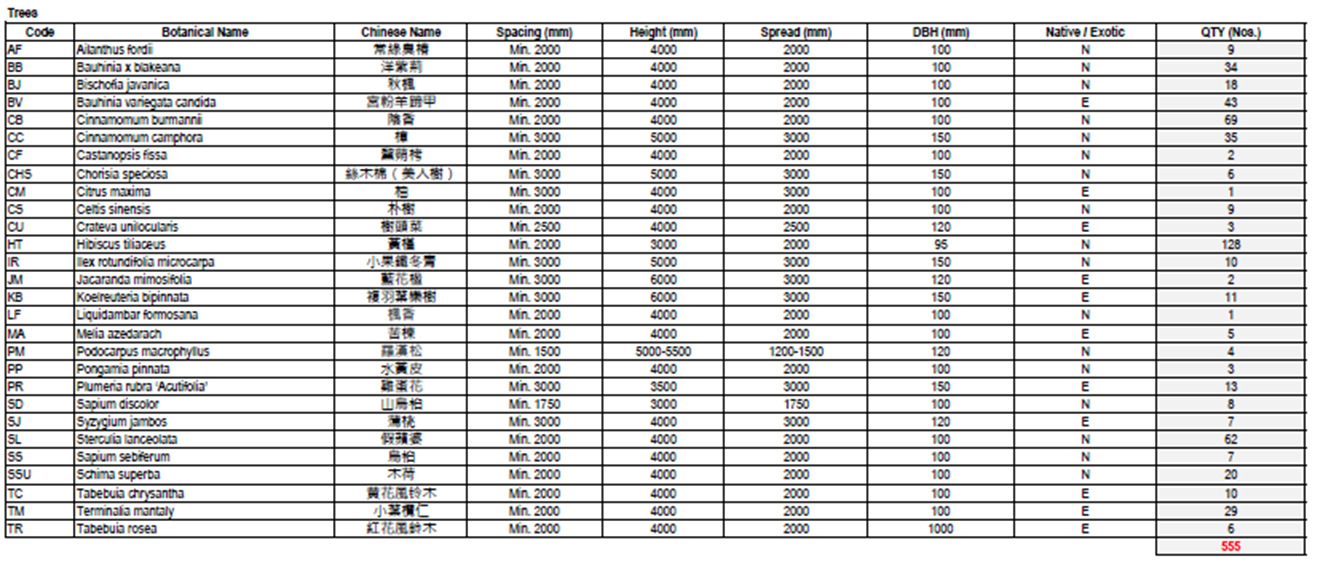
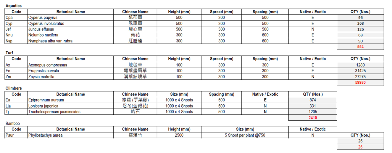
Tables 5.1 and 5.2 below provide a snapshot of the proposed greening information.
Table 5.1 Proposed Greening Summary Table
|
Description |
Quantity |
|
|
1 |
Numbers of Trees |
595 nos. |
|
2 |
Area of Shrub and Ground Cover |
27,186 m2 |
|
3 |
Area of Vertical Greening |
12,693 m2 |
Table 5.2 Proposed Greening Tables (Extracts from Annex B)
Landscape Master Plan
Reception Pavilion
IWMF Substation
Turbine Hall
Process Building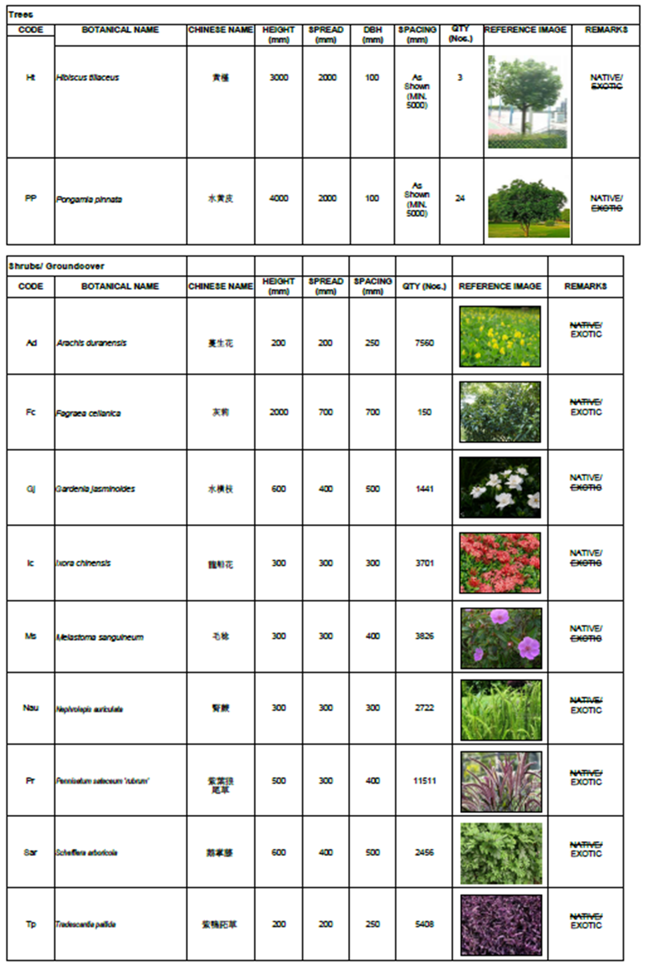
MTP/WTP Building
Administration Building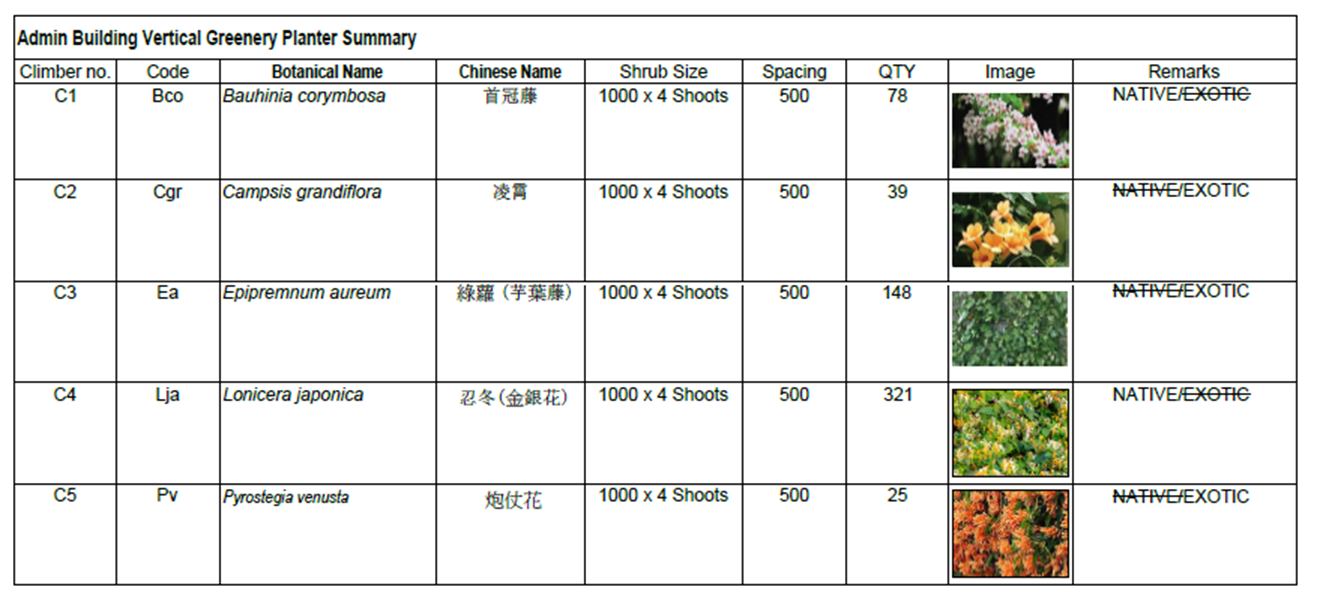
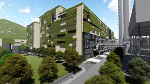
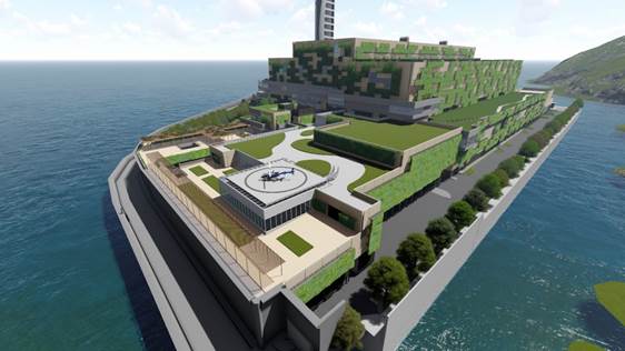
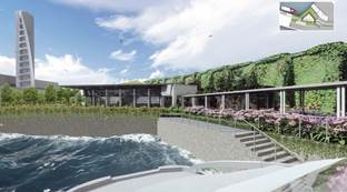
The context of Shek Kwu Chau and its steeply sloping densely vegetated and rugged coastline with large outcrops of yellowish decomposed granite has been the point of inspiration for the development of the aesthetic design language for the IWMF.
The IWMF exteriors have been devised to mimic the variable outlook of the island and blend into the surrounding green environment in a similar manner to that which can be observed on Shek Kwu Chau island where this occurs naturally. The aesthetic treatment of the new construction will therefore respond to its natural setting and scenery in a manner which is already established and apparent. Refer to Figure 6.1.
The building layout/height in the current submission defers from that in the Approved EIA Report due to further design developments to the proposed enhancement of the seawall/wavewall and visitor path, which will have the aim to provide a more close-up experience for the visitors to the seafront. Therefore, the proposed buildings/structures have been further designed to supplement this aim. Furthermore, the seawall/wavewall has now introduced the timber-colored hull-liked pattern (refer to Figure 6.1) to amplify the sailboat/marine theme of the whole aesthetic design of the IWMF, in order to enhance the blending into the surrounding environment. To compliment this marine feature, both sides of this timber hull will feature undulating patterns with varying shades of blue color to mimic a vibrant sea.
Furthermore, the Administration Building has been reorientated 90 degrees such that the landscape courtyard will be combined and enlarged as one. The visitor path that connects to the Administration Building was realigned and incorporated with the landscape Sky Deck projected from the high seawall to create an interesting landscape design. The helipad at the MTP/WTP Building adjacent to the Administration Building is adjusted according to the current building design and comments from the Civil Aviation Department and Government Flying Services.
Landscape features and observation deck of the Chimney are proposed to be relocated and incorporated into the south facing seawall forming part of the external visitor’s path, named as “Sky Deck”. The current design is considered to be more environmentally friendly, in which the configuration of the Chimney stack is streamlined into an aerodynamic form to address the wind load effectively. Furthermore, the landscaped Sky Deck is more accessible for the public and from the maintenance point of view. Other design intents are elaborated below:
- To accentuate the iconic form of the Chimney, asymmetrical external aluminum panels are cladded on its concrete structure to resemble a sail of a boat to form a feature in order to symbolise the Hong Kong spirit overcoming high and low tides for a better future. Being the first facility of its kind, the endorsed concept of IWMF1 is “一帆風順 領航前行” (aka “smooth sailing, with great stewardship forward”);
- The cladding is slightly projected from the concrete structure, so that its shadow will be cast on the stack with slightly varied under different weather conditions and time of day, thus creating interesting visual impressions;
- For the front and back of the seawalls facing the South China Sea, various shades of blue in a wavy pattern and a brown paint will be applied on the back and part of the front seawall respectively to represent a timber boat sailing on the sea;
- Color pattern of the wavewall will breakdown the scale of the facility’s enormity when visitors come near to the artificial island during a visit;
- The said design concept and images of the Chimney have been presented to the stakeholders, including the Community Liaison Group, who have no objections on the updated design intention; and
- The avoid maintenance issues on the external paint, budget consideration and to facilitate the programme, it is proposed to utilise the cladding and painted seawall rather than the gradual paint on the stack to enhance the overall visual impact of the complex.
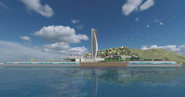
Figure 6.1 General Aesthetic treatment of the IWMF development featuring the timber hull-like seawall/wavewall in the foreground, landscaped development with vertical greening in the midfield and the iconic sail format chimney structure.
6.2 Subtle Variegation in Colours of the Façades to Rhyme with NatureThe façade cladding of the IWMF will comprise prefabricated cladding panels and precast concrete panels finished in subtly-different shades of yellowish grey that will match precisely the weathering colours of the existing granite out-crops of Shek Kwu Chau. In order to complement the variety of the surrounding environment, the applications of aluminium cladding for the Chimney and precast concrete façade panels for other buildings on the IWMF Campus have been designed for.
6.3 Variety in Form of the Façade to Rhyme with NatureThe façade cladding of the IWMF has been developed to provide a deep textural surface. It will not simply comprise a uniform panel but will comprise a modular system of cantilevered planters that will create an apparently random façade mimicking the outcrops and weathered recesses that evoke the natural coastline of Shek Kwu Chau.
6.4 Vertical Greening to be an Integral Part of the ArchitectureFinally, a façade expressing extensive vertical greening, which will comprise not just a single species but a variety of climbers will be presented in the array of surface mounted planter boxes. The variety of species will generate an arrangement of varied and semi random colours to provide a rich, lush and verdant envelope of dense vegetation that will closely echo the varied range of natural vegetation currently present on Shek Kwu Chau. The vertical greening system is served by a drip-fed recycled water irrigation system located on the planter surface, with a vertical drainage system that is concealed within the precast concrete panel (openable for maintenance). The vertical greening façade is also accessible by cherry pickers, and cat ladders from the roof to connected maintenance platforms (of no less than 600mm wide) for maintenance purposes.
Over time and, as the greening becomes established, the visual affinity of the IWMF and with Shek Kwu Chau will become enhanced. The natural and built components of the newly created visage will become fully integrated and a trend towards interdependence will become established. Refer to Drawing nos. IWMF1_14-136_990_124101, IWMF1_14-136_990_124102, IWMF1_14-136_610_014201, IWMF1_14-136_500_114201, IWMF1_14-136_500_114202, IWMF1_14-136_500_114203, IWMF1_14-136_700_114201, IWMF1_14-136_700_114202, IWMF1_14-136_700_014203, IWMF1_14-136_300_114201 , IWMF1_14-136_300_114202 , IWMF1_14-136_300_114203, IWMF1_14-136_500_114201, IWMF1_14-136_800_114202, and IWMF1_14-136_800_114203 in Annex B for the building elevations demonstrating the prescribed theme of the vertical greening.
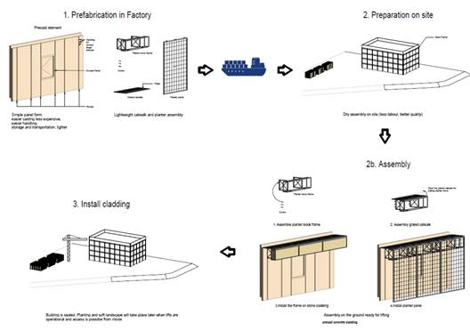
Figure 6.2 Green wall modular concept
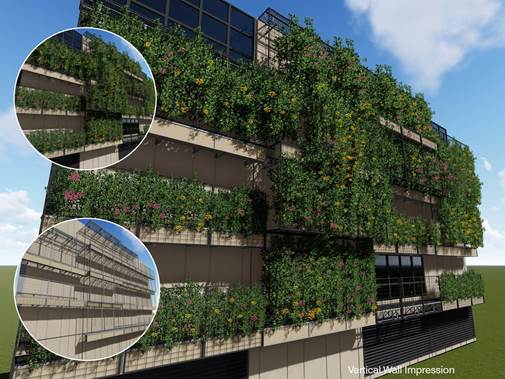
Figure 6.3 Mature green wall overall impression
6.5 Borrowed Views of the Surrounding Geography and Landscape Provide Visual Connections to Shek Kwu Chau
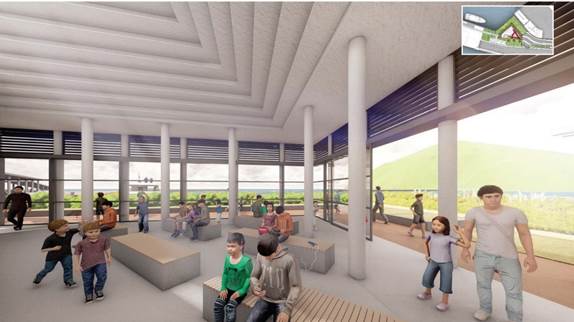
Public spaces throughout the interior of the IWMF will be provided with windows designed to capture panoramic views looking towards both the South China Sea and the coastline of Shek Kwu Chau. The views towards the Island will flood into the spacious and bright viewing arenas to form an integral and unforgettable part of the visitor experience to the facility. This will provide a sense of the connection between the IWMF and its neighbouring context. Through experiencing the building the visitors will conclude that the IWMF does not turn its back on Shek Kwu Chau but, through its design, it will deferentially acknowledge and blend in with Shek Kwu Chau as an indispensable and indistinguishable natural and green neighbour.
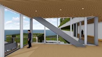
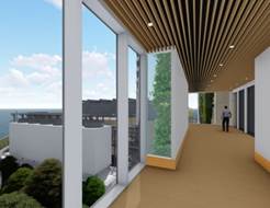
Figure 6.4 General outlook from the visitor viewing gallery
6.6 Avoidance of Industrial Impression in Chimney DesignThe incorporation of a cladding system has been key to the development of the aesthetic model for the chimney. A curved profile in the apparent form of a large sail has been selected to soften the vertical form of the chimney. Contrasting colours to the green building facades have been selected to provide a wide contrast and nautical flavour to the structure. The facility will be a functional component of the development and will incorporate a maintenance staircase. The chimney design will concurrently transform the chimney into an attractive and iconic architectural feature.
Although the functional requirements of the multi stack chimney are completely fulfilled the clean modern design of the elliptical wind shield will impart an impression of purposeful, welcoming, civic elegance that is antithetical to the impression of a purely industrial facility.
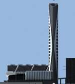
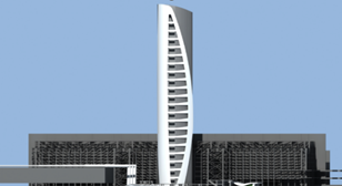
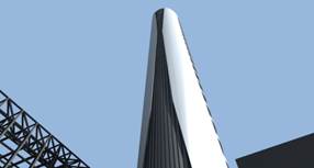
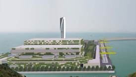
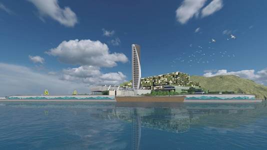
Figure 6.5 Chimney concept
6.7 Aesthetic design of breakwaterThe breakwater structure is required to provide protection from the marine environment at the site. Wave activity can be intense during typhoon conditions and the structure has been designed to be robust. The top surface of the structure will be armoured with interlocking prefabricated concrete armouring units designed to minimize the demand for large quarried armourstone which could not otherwise be achieved without significant environmental impact. The proposed visual appearance of the armoured breakwater structures is illustrated in Figures 6.6. Acc ordingly, interlocking concrete armouring units similar to those adopted at High Island Reservoir will be deployed (for reference photos of these interlocking concrete armouring units please refer to www.wsd.gov.hk/filemanager/common/pdf/PublicRelation/High%20Island%20Reservoir.pdf Section 7 – Cofferdam). The units will weather and be colonized by a diverse shoreline flora and fauna to match the adjacent exposed rocky shoreline in a manner similar to the units at High Island where this type of armouring unit is deemed to be compatible with the rugged country park environment.
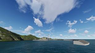
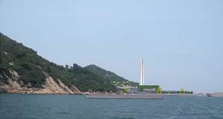
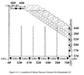
Figure 6.6 Visual appearance of the Breakwaters
In accordance with the approved Fisheries Enhancement Programme of the Further Environmental Permit No. FEP-01/429/2012/A, ecological enhancement design features for breakwater and Eco-shoreline will be adopted. Below tidal level the design will introduce numerous horizontal crevices into the pre-casted concrete blockwork to make the breakwater and shoreline more harmonised with the natural shoreline. Development of a sustained and diverse marine ecology is expected to arise as a result.
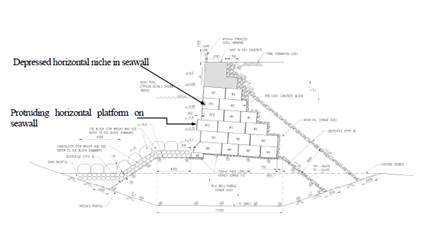
Figure 6.7 a) Eco-shoreline concept along the seawall facing Shek Kwu Chau Island
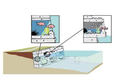
Figure 6.7 b) Eco-shoreline concept along the seawall facing Shek Kwu Chau Island
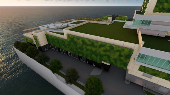
The blockwork seawalls facing SKC island will be specifically developed as an eco-friendly shoreline. As noted above, for areas located below tidal level the design has been developed to introduce numerous horizontal crevices and pockets into the pre-casted concrete blockwork to make the seawall and breakwater landward shorelines more ecologically friendly. The enhanced surface of the seawall is aimed at developing a sustained and diverse marine ecology. Refer to Figures 6.8 and 6.9.

Figure 6.8 Overhead view of Seawalls and Breakwater
Figure 6.9 Seawall Configuration
6.8 Aesthetic design building structures 6.8.1 Main Process Building
The dominant building structure within the development will be the main process building. This structure will be large and will house the main incineration plant, equipment, boilers and flue gas processing equipment. The proposed aesthetic outlook of the building is illustrated in Figures 6.10. Green façades and a green roof at the lower floor will be adopted to soften the impact and massing of the structure. The proposed aesthetic outlook of the green roof is illustrated in Figures 6.11.
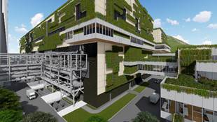
Figures 6.10 depicting (clockwise from top left corner) the a) Southeast, b) Northwest, c) North and d) South elevations of the Main Process Building
Figures 6.10 depicting southwest elevations of the Main Process Building
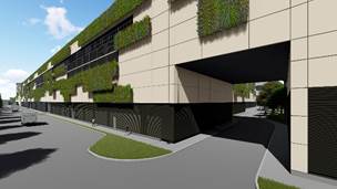
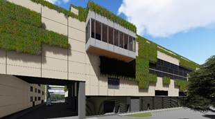
The Materials Treatment Building (MT) and Water Treatment Plant Building (WTP) form the primary backup plant enclosures supporting the process. This building will have the second largest footprint on the site. The building will be treated with the same aesthetic approach as the main building to provide a matching and consistent visual appearance to the architecture on the site.
The proposed aesthetic outlook of the building is illustrated in Figures 6.12.
Figures 6.12 Views of the MT and WTP Building
Figures 6.12 Views of the MT and WTP Building
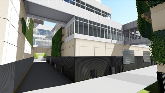
6.8.3 Administration Building
The administration building will be interconnected with the main process building, MT and WTP buildings by means of elevated footbridges. These will provide a focused path for visitors. The building will be integrated with these interfacing buildings being treated with a sympathetic aesthetic approach to the main building.
The proposed aesthetic outlook of the building is illustrated in Figures 6.13.
Figures 6.13 Administration Building
6.8.4 Turbine Hall, ACC and CCCWThe Turbine Hall, ACC and CCCW structures comprise supporting plant enclosures within the facility. These structures will have a differing and more industrial outlook as a result of their functionality. The Turbine Hall, ACC and CCCW will be functional plant enclosures rather than being building structures. They will be intimately endowed with external interconnecting pipework as an integral part of their operational requirements. Their architectural treatment will necessarily be influenced by the connecting piping and cabling making them less receptive to the architectural detailing adopted for the other building structures across the site. The plant enclosures will adopt a styled aesthetic approach to blend in with the main building to provide a complementary visual appearance to the architecture on the site. Furthermore, heavy standard/semi-mature standard trees are specially selected to be planted adjacent to the side of the ACC that faces the Visitor Path. Therefore these trees, which when matured will have a height of no less than 15m, will provide the visitor a view that begins at the biologically diverse and colorful west courtyard, followed by the ornamental roof garden of the IWMF Substation, then finally arriving at the lush greenery beset by these tall trees. An indication of the approach is provided in the overall image included in Figure 1.2. For the wind wall of the ACC, a paint finish (of RAL7035) will be provided to complement the aforesaid more industrial outlook.
6.8.5 IWMF Substation BuildingThe IWMF Substation Building will be key to the power from waste focus of the project and will house the interfacing connection to the CLP grid. This building will have a small footprint on the site but will be a key feature. The building will be treated with the same aesthetic approach as the main building to provide a matching and consistent visual appearance to the architecture on the site.
The proposed aesthetic outlook of the building is illustrated in Figures 6.14.
Figures 6.14 IWMF Substation building
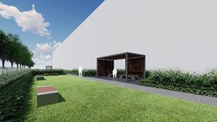
6.8.6 Reception PavilionThe reception pavilion will be located adjacent to the marine access facilities and passenger berth. The structure will generate the first view of the IWMF facility and will house waiting and educational exhibits to introduce the power from waste focus of the project. This building will have a small footprint on the site but will be a key feature. The building will have an open and inviting architectural aesthetic approach.
The proposed aesthetic outlook of the building is illustrated in Figures 6.15.
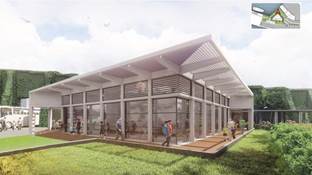
Figures 6.15 Reception Pavilion
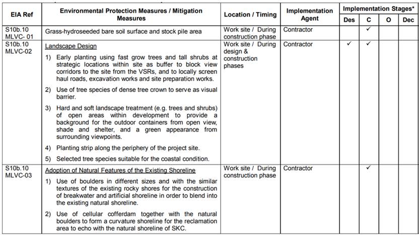
7 LANDSCAPE AND VISUAL IMPACT AND MITIGATION MEASURES 7.1 Landscape and Visual Design Measures in EIA & EM&AIn Section 10b.10 of the approved EIA report and Section 13.2.8 of the EM&A Manual, the following design measures as listed in Table 7.1 below are proposed as landscape and visual impact mitigation measures. These mitigation measures have been considered and will be adopted as far as practicable.
Table 7.1 Mitigation Measures (See Figure 6-1 & 6-2 and Annex B Drawing no. IWMF1-LVP-01)
|
ID No. |
Construction Phase Mitigation Measures in the Approved EIA |
Implementation Details under this Plan |
|
|
Mitigation for both Landscape & Visual Impacts |
|||
|
MLVC-01 |
Grass-hydroseeded bare soil surface and stockpile area |
KSZHJV will grass-hydroseeded bare soil surface and stockpile areas as appropriate during the construction period. |
|
|
MLVC-02 |
Landscape Design 1) Early planting using fast grow trees and tall shrubs at strategic locations within site as buffer to block view corridors to the site from the VSRs, and to locally screen haul roads, excavation works and site preparation works. |
Early planting using fast growing trees and tall shrubs in the visitor zone with the theme of Dense Forest Journey will provide a rich green environment for the visitors and will mitigate visual impact from the seawalls. (See Figure 6-1, 12, 13 and 14, and drawing no. IWMF1_10-130_990_000200 and IWMF1-LVP-01) A row of tree planting will be introduced along the north-east edge to screen road and mitigate visual impact to VSR from SKC. |
|
|
2) Use of tree species of dense tree crown to serve as visual barrier. |
Use of tree species with dense tree crowns (e.g. Cinnamomum burmannii, Hibiscus tiliaceus, etc.) will serve as a visual barrier. (See Figure 6.13, and drawing no. IWMF1_10-130_990_000200 and IWMF1-LVP-01) |
|
|
|
3) Hard and soft landscape treatment (e.g. trees and shrubs) of open areas within development to provide a background for the outdoor containers from open view, shade and shelter, and a green appearance from surrounding viewpoints. |
Accessible green roofs will act as an elevated park intended for use by visitors and staff a garden, with vertical greening, shrubs and tree planting, pathways, seating and shade structures. Dense tree planting will provide a lush and green appearance whilst the Tree Top Walk and Viewing Platform will offer panoramic ocean views for the visitors. (See Figure 6.12, and drawing no. IWMF1_10-130_990_000200 and IWMF1-LVP-01) |
|
|
|
4) Planting strip along the periphery of the project site. |
A planting strip is proposed along the southern and north-eastern periphery of the project site to mitigate visual impact to VSRs as identified in the approved EIA report. |
|
|
|
5) Select tree species suitable for the coastal condition. |
Coastal buffer planting such as the Syzygium jambos & Hibiscus tiliaceus are proposed due to their high salinity tolerance and their ability to thrive under sea shore conditions. |
|
|
|
MLVC-03 |
Adoption of Natural Features of the Existing Shoreline 1) Use of boulders in different sizes and with the similar textures of the existing rocky shores for the construction of breakwater and artificial shoreline in order to blend into the existing natural shoreline. |
Ecologically enhanced design features will be constructed for the breakwater and seawall facing the existing shoreline of Shek Kwu Chau. These will make reference to the conceptual design of eco-shoreline as described in Section 6.7 (see Figure 6.7, and drawing no. IWMF1_10-130_990_000200 and IWMF1-LVP-01). Details of the seawall and breakwater configuration are included in Annex C. Whilst natural boulders cannot be practically implemented as sea defences for the breakwater under such a hostile wave climate interlocking armouring units similar to those at High Island Reservoir will be adopted to facilitate colonisation by a rich biodiverse flora and fauna whilst providing robust wave resistant sea defences. |
|
|
2) Use of cellular cofferdam together with the natural boulders to form a curvature shoreline for the reclamation area to echo with the natural shoreline of SKC. |
|
||
|
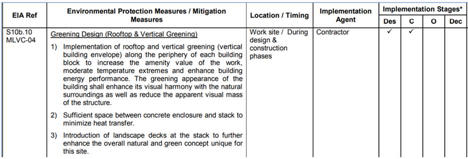
MLVC-04 |
Greening Design (Rooftop & Vertical Greening) 1) Implementation of rooftop and vertical greening (vertical building envelope) along the periphery of each building block to increase the amenity value of the work, moderate temperature extremes and enhance building energy performance. The greening appearance of the building shall enhance its visual harmony with the natural surroundings as well as reduce the apparent visual mass of the structure. |
Green roofs are proposed on the roofs of buildings within the Visitor Zone, many of which will be designed as accessible green roofs. These green roofs not only increase amenity value, enhance micro-climate and visual harmony with the surroundings, but also provide recreational value as roof garden and function as connections between buildings. (See Figure 6.10 b, and drawing no. IWMF1_10-130_990_000200 and IWMF1-LVP-01) For details of the green roofing refer to Annex B The vertical greening system integrates planter boxes into the building façade. These modular panels of standard size will provide overall green and lush appearance for the whole site. (See Figures 6-2 and 6-3, and drawing no. IWMF1_10-130_990_000200 and IWMF1-LVP-01) Green roofing will not be incorporated in the Main Process Building, Air Cooled Condensers Building and Turbine Hall due to equipment and operational constraints explained in Section 5.7. Refer also to Annex B. |
|
|
2) Sufficient space between concrete enclosure and stack to minimize heat transfer. |
Wide circulation accesses have been provided between the main process building enclosure and the chimney to minimize heat transfer and accumulation. Refer to Annex B. |
|
|
|
3) Introduction of landscape decks at the stack to further enhance the overall natural and green concept unique for this site. |
Sky gardens are introduced at the seaward facing portion of the Administration Building and the MTP/WTP Building to allow for additional greening for enhancing the aesthetic quality and the overall natural and green concept unique to this site (see Figures 1.2, 1.3, 6.11 and 6.12, and drawing no. IWMF1_10-130_990_000200 and IWMF1-LVP-01). |
|
|
|
Mitigation for Visual Impacts |
|||
|
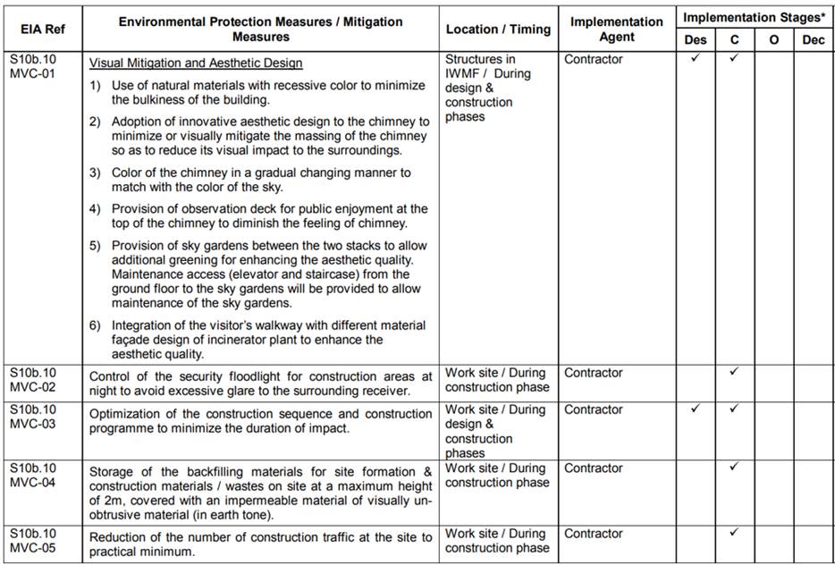
MVC-01 |
Visual Mitigation and Aesthetic Design 1) Use of natural materials with recessive colour to minimize the bulkiness of the building. |
The Façade cladding of the IWMF will comprise prefabricated cladding panels finished in subtly different shades of yellowish grey that will match precisely the weathering colours of the existing granite out-crops of Shek Kwu Chau. KSZHJV will adopt natural materials for construction of cladding panels wherever possible (see Figures 6.8.2, 6.11 and 6.12, and drawing no. IWMF1_10-130_990_000200 and IWMF1-LVP-01) |
|
|
2) Adoption of innovative aesthetic design to the chimney to minimize or visually mitigate the massing of the chimney so as to reduce its visual impact to the surroundings. |
The incorporation of an iconic and contrasting sail resembling structure will provide a themed distraction from industrial context of the chimney structure. This approach has achieved approval from stakeholders by relating to the maritime communities. . The structure will provide an important amenity feature and concurrently transforms the chimney into an attractive architectural feature (see Figures 1.3, 6.1, 6.6, 6.8, 6.9 and 6.10, and drawing no. IWMF1_10-130_990_000200 and IWMF1-LVP-01). |
|
|
|
3) Colour of the chimney in a gradual changing manner to match with the colour of the sky. |
The cladding of the chimney is designed to be held by a steel subframe at a horizontal distance away from the main concrete structure, which will provide a shading projected onto the main concrete structure at different hours of the day, its shadow will thus providing the gradual changing manner (see Figures 1.3, 6.1, 6.6, 6.8, 6.9 and 6.10, and drawing no. IWMF1_10-130_990_000200 and IWMF1-LVP-01). The cladding is slightly projected from the concrete structure, so that its shadow will be cast on the stack with slightly varied under different weather conditions and time of day, thus creating interesting visual impressions; |
|
|
|
4) Provision of observation deck for public enjoyment at the top of the chimney to diminish the feeling of chimney. |
The design of the chimney has incorporated a contrasting sail like concept to provide a varied and aesthetically pleasing outlook matching the sailboat/marine theme to diminish the feeling of a chimney which has been endorsed by the local community. Furthermore, the visitors will now have more observation deck areas at the Administration Building and MTP/WTP Building as mentioned in item 5 below (see Figures 1.3, 6.1, 6.6, 6.8, 6.9 and 6.10, and drawing no. IWMF1_10-130_990_000200 and IWMF1-LVP-01). Landscape features and observation deck of the Chimney are proposed to be relocated and incorporated into the south facing seawall forming part of the external visitor’s path, named as “Sea Deck with Sea Pavilion”. The current design is considered to be more environmentally friendly, in which the configuration of the Chimney stack is streamlined into an aerodynamic form to address the wind load effectively. Furthermore, this landscaped Sky Deck with Sea Pavilion is more accessible for the public and from the maintenance point of view; |
|
|
|
5) Provision of sky gardens between the two stacks to allow additional greening for enhancing the aesthetic quality. Maintenance access (elevator and staircase) from the ground floor to the sky gardens will be provided to allow maintenance of the sky gardens.
|
Sky gardens are introduced at the seaward facing portion of the Administration Building and the MTP/WTP Building to allow for additional greening for enhancing the aesthetic quality. Elevator inside the Administration Building and an external staircase will provide maintenance access from the ground floor to the sky gardens (see Figures 1.2, 1.3, 6.11 and 6.12, and drawing no. IWMF1_10-130_990_000200 and IWMF1-LVP-01). |
|
|
|
Mitigation for Visual Impacts |
|||
|
MVC-01 |
6) Integration of the visitor’s walkway with different material façade design of incinerator plant to enhance the aesthetic quality. |
The Administration Building, the Mechanical Treatment Building and viewing gallery linking the Reception Hall and Main Process Building will comprise over a number of different levels of terraces resulting in an undulating building form that is highly sympathetic to the natural topography of Shek Kwu Chau (see Figures 6.1, 6.8, 6.10, 6.11 and 6.12, and drawing no. IWMF1_10-130_990_000200 and IWMF1-LVP-01). The pedestrian pathway and Sky Garden structure that has been designed to connect the administration building with the reception pavilion at the passenger reception pier will start at the second-floor roof garden of the Administration Building before continuing as a gentle slope set atop landscaped berms all the way to the ferry pier at +6.00mPD. This will provide a physical connection between the IWMF’s natural (forested berms) and building (landscaped terrace roofs green walls) topographies. Refer to Annex B. In this way the building forms will integrate with the natural topography of Shek Kwu Chau and the sea. |
|
|
MVC-02 |
Control of the security floodlight for construction areas at night to avoid excessive glare to the surrounding receiver. |
KSZHJV will restrict and control the security floodlighting by adjusting the angle of floodlight so as to minimise possible glare as far as possible. |
|
|
MVC-03 |
Optimization of the construction sequence and construction programme to minimize the duration of impact. |
KSZHJV propose to optimize the construction sequence and construction programme to minimize the duration of construction impacts. |
|
|
MVC-04 |
Storage of the backfilling materials for site formation & construction materials / wastes on site at a maximum height of 2m, covered with an impermeable material of visually un-obtrusive material (in earth tone). |
KSZHJV will cover the backfilling materials during site formation & construction materials / wastes with green tarpaulins or by using hydroseeding. Refer to Annex B. |
|
|
MVC-05 |
Reduction of the number of construction traffic at the site to practical minimum. |
KSZHJV will minimise construction traffic on the site within practical limitations. |
|
|
ID No. |
Operation Phase Mitigation Measures |
Implementation Details under this Plan |
|
|
Mitigation for both Landscape & Visual Impacts |
|||
|
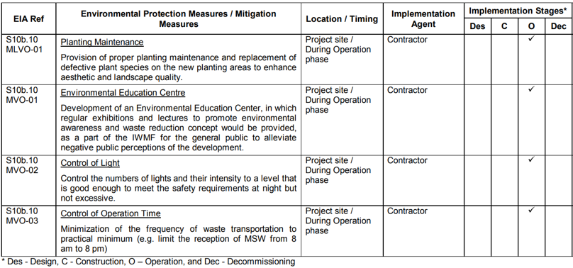
MLVO-01 |
Planting Maintenance Provision of proper planting maintenance and replacement of defective plant species on the new planting areas to enhance aesthetic and landscape quality. |
Proper intervention and planting maintenance will be provided to ensure the landscaping planting works thrive. Refer to principles and schedule in Sections 7.4 and 7.5. |
|
|
Mitigation for Visual Impacts |
|||
|
MVO-01 |
Environmental Education Centre Development of an Environmental Education Center, in which regular exhibitions and lectures to promote environmental awareness and waste reduction concept would be provided, as a part of the IWMF for the general public to alleviate negative public perceptions of the development. |
An Environmental and Waste Management Education Centre located inside the Administration Building will be established as a part of the IWMF for the general public. This should help to alleviate possible negative public perceptions of the development. |
|
|
MVO-02 |
Control of Light Control the numbers of lights and their intensity to a level that is good enough to meet the safety requirements at night but not excessive. |
KSZHJV will control the numbers of lights and their intensity to a level that is adequate to meet the safety requirements at night to avoid excessive glare to the surrounding receivers. |
|
|
ID No. |
Operation Phase Mitigation Measures |
Implementation Details under this Plan |
|
|
MVO-03 |
Control of Operation Time Minimization of the frequency of waste transportation to practical minimum (e.g. limit the reception of MSW from 8 am to 8 pm) |
KSZHJV will optimise the frequency of waste transportation to a practical minimum (e.g. limit the reception of MSW from 8am to 8pm). |
|
Weekly site audits will be conducted by the project Environmental Team (ET) in accordance with EM&A manual Section 13.2.8 to ensure appropriate mitigation measures are properly implemented.
The ET will monitor the implementation of environmental mitigation measure and will assess their effectiveness. They will advise the Contractor on environmental awareness and enhancement matters.
7.3 Implementation ProgrammeAn implementation programme as required by TM-EIAO is presented below:
Table 7.2 Project Implementation Schedule
A full Operations and Maintenance (O&M) Manual will be prepared describing in detail all routine and periodic maintenance inspections and operations to be carried out by the O&M agent and/or his contractors. Typical operations and scheduling for both hard and soft landscape element are illustrated in the following tables:
Table 7.3 Hard Landscape Maintenance Principles
|
Irrigation System |
|
|
Operation : |
Oversee system and adjust timers as required |
|
Adjust : |
Adjust valve water flow rates in field twice a year March and October |
|
Repair : |
Repair and replace fittings and pipework as required |
|
Lighting |
|
|
Repair : |
Fittings as required |
|
Replace : |
Replace bulbs as required |
|
Hard Paving |
|
|
Repair : |
Check and maintain all paving and repair as required |
|
Clear : |
Remove debris from drains twice a year and routinely check after storms |
|
Water Features |
Maintenance contract/ program should be arranged and agreed with a program to be prepared by Water Feature Contractor. Additional maintenance visits as required. |
Table 7.4 Hard Landscape Maintenance Schedule
|
|
JAN |
FEB |
MAR |
APR |
MAY |
JUN |
JUL |
AUG |
SEP |
OCT |
NOV |
DEC |
|
Irrigation System |
|
|
|
|
|
|
|
|
|
|
|
|
|
Operation |
* |
* |
* |
* |
* |
* |
* |
* |
* |
* |
* |
* |
|
Adjust valves |
|
|
* |
|
|
|
|
|
|
* |
|
|
|
Repair |
* |
* |
* |
* |
* |
* |
* |
* |
* |
* |
* |
* |
|
Lighting |
|
|
|
|
|
|
|
|
|
|
|
|
|
Repair |
* |
* |
* |
* |
* |
* |
* |
* |
* |
* |
* |
* |
|
Replace |
* |
* |
* |
* |
* |
* |
* |
* |
* |
* |
* |
* |
|
Hard Paving |
|
|
|
|
|
|
|
|
|
|
|
|
|
Repair |
* |
* |
* |
* |
* |
* |
* |
* |
* |
* |
* |
* |
|
Clear |
* |
* |
* |
* |
* |
* |
* |
* |
* |
* |
* |
* |
|
Water Features |
|
* |
|
|
|
|
|
* |
|
|
|
|
Table 7.5 Soft Landscape Maintenance Principles
|
Watering : |
Watering to all plants to ensure satisfactory growth and health (manual and automatic irrigation) |
|
Fertilizing : |
Twice yearly November and March with emphasis on March application |
|
Fungicide/ Insecticide : |
Spray as necessary or 3 monthly intervals with approved non-toxic pesticides |
|
Weeding : |
To be carried out by hand or by mechanical means in such a manner that damage to the grass and planted areas will not be caused. |
|
Securing : |
Adjust tree stakes, guys and ties as required for safety and avoid chaffing of bark |
|
Repairing : |
After exceptional weather conditions replace dead plants, repair damaged plants, bed in all plants that have blown over, firm up all other plants and immediately thereafter, remove dead plants and plant debris from the site |
|
Removal : |
Remove all litter and debris |
|
Pruning : |
Prune Shrubs and ground covers twice a year in March and November |
|
Pruning : |
Prune trees/limb overhanging branches, as required for safety |
|
Mowing : |
Mow grass twice a year in March and October |
|
Pest / Fungal Check and Control |
Conduct in a monthly basis |
|
Inspection post Typhoon or inclement weather |
Conduct after typhoon and inclement weather |
|
Tree Risk Assessment |
Conduct once in a year |
Table 7.6 Soft Landscape Maintenance Schedule
|
|
JAN |
FEB |
MAR |
APR |
MAY |
JUN |
JUL |
AUG |
SEP |
OCT |
NOV |
DEC |
|
Watering |
|
|
|
|
|
l |
l |
l |
l |
|
|
|
|
Fertilizing |
|
|
l |
|
|
|
|
|
|
|
l |
|
|
Fungicide / Insecticide |
|
|
l |
|
|
|
|
|
l |
|
|
l |
|
Weeding |
l |
l |
l |
l |
l |
l |
l |
l |
l |
l |
l |
l |
|
Securing* |
l |
l |
l |
l |
l |
l |
l |
l |
l |
l |
l |
l |
|
Repairing* |
l |
l |
l |
l |
l |
l |
l |
l |
l |
l |
l |
l |
|
Cleaning* |
l |
l |
l |
l |
l |
l |
l |
l |
l |
l |
l |
l |
|
Pruning Shrubs / Ground Covers |
|
|
l |
|
|
|
|
|
|
|
l |
|
|
Pruning Trees* |
l |
l |
l |
l |
l |
l |
l |
l |
l |
l |
l |
l |
|
Mowing |
|
|
l |
|
|
|
|
|
|
l |
|
|
Note:
* - Conduct when necessary
7.5 Maintenance Responsibilities for Landscape WorksMaintenance of Vegetation and Hard Landscape Features will be undertaken by the JV as a contractual requirement for the project prior to it being handed over to EPD for future maintenance after the expiration of the operation stage.
8 CONTAINER STORAGE
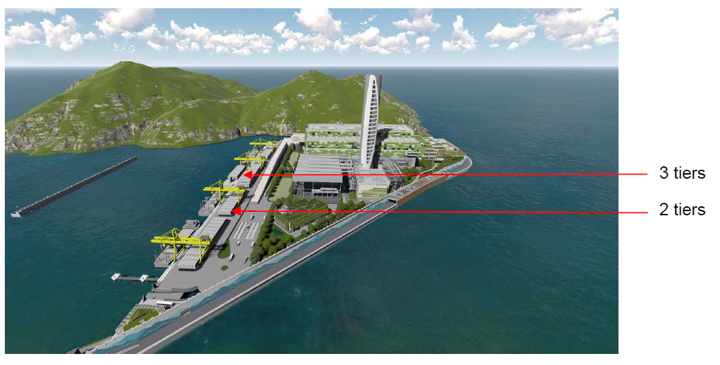
As part of the operational requirements of the facility it is necessary to make provision for storage of a significant number of containers. These containers will be stored in the area adjacent to the vessel offloading berths to be within reach of the 4 main offloading cranes. The EIA made recommendations to limit the height of container storage to stacking not exceeding 2 tiers in height. This requirement was proposed to limit the visual impact of the container storage. However, the limited size of the site dictates that storage of containers to 3 tiers high in selected areas will be required to meet operational requirements. The visual appearance of the container stacking arrangement whether 2 or 3 tiers when assessed from the EIA designated visually sensitive receivers VSR1 – VSR14 incl. will be minimal as the effect will be observed from just too far away.
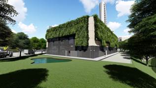
Accordingly, photomontages illustrating the changes brought about by increasing the container stacking height from 2 to 3 tiers at closer range are presented in Figures 8.1 to 8.4. It can clearly be seen that the impact of increasing the container stacking height from 2 to 3 tiers will be minimal and acceptance for this amendment is made accordingly.
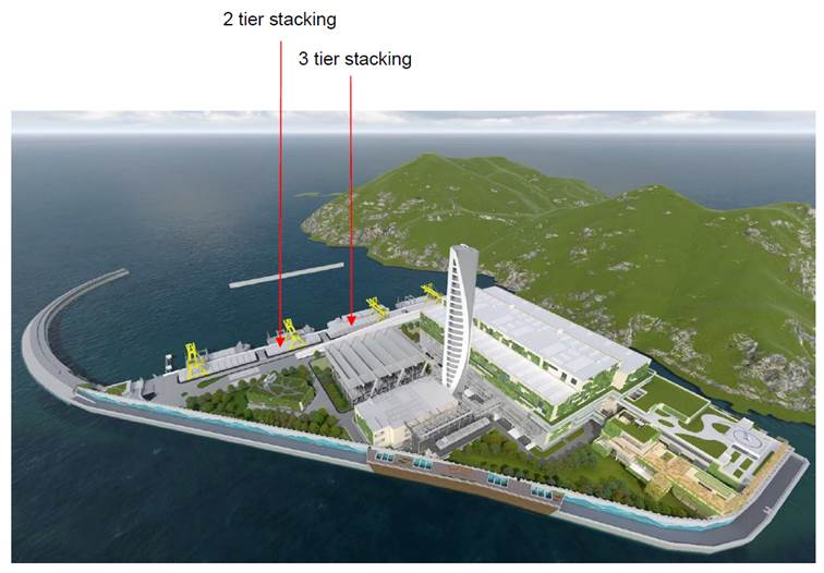
Figure 8.1 Visual impact associated with stacking containers to 2 and 3 tiers
![]()
![]()
![]()
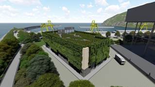
Figure 8.2 Visual impact associated with stacking containers to 2 and 3 tiers
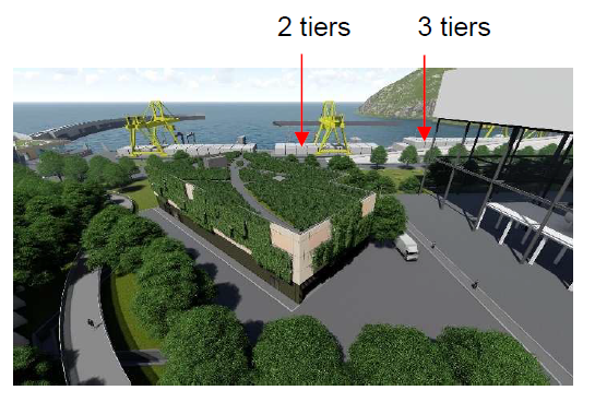
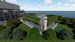
Figure 8.3 Visual impact associated with stacking containers to 2 and 3 tiers
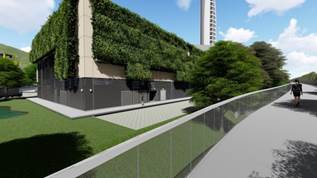
Figure 8.4 Visual impact associated with stacking containers to 3 tiers (3 tiers not visible from VSR2)
9 CONCLUSIONLandscape and visual mitigation measures proposed in the approved EIA and FEP have been considered and adopted in the current scheme with strategic hard and soft landscape design, in particular on vertical surfaces and their edge treatment, green roofs and vertical greening. These design elements are still under the design and development process. They will be submitted separately once available and prior to the construction of the works. It has been demonstrated that the increase of container stacking in selected areas from 2 to 3 tiers will generate an almost imperceptible visual impact from the EIA VSR locations and a minimal impact from closer range. Endorsement of the increase from 2 to 3 tiers is therefore sought.