Revision History
|
5 |
Revised as per EPDs comment |
22/10/2018 |
RKS |
GCA |
|
4 |
Revised as per ERMs comment |
05/9/2018 |
RKS |
GCA |
|
3 |
Revised as per EPDs comment |
20/8/2018 |
RKS |
GCA |
|
2 |
Revised as per IECs comment |
25/5/2018 |
RKS |
GCA |
|
1 |
Revised as per ETs and IECs comment |
15/5/2018 |
RKS |
GCA |
|
0 |
First issue |
20/04/2018 |
RKS |
GCA |
|
REV |
Description of Modification |
Date |
Prepared by |
APproved by |
CONTENTS
2 DESIGN STANDARDS AND CODES OF PRACTICE
3.2 Wastewater Sources, Flows and Characteristics
4.2 Pre-treatment Works Systems and Equipment
4.3 Secondary Treatment Systems
4.3.1 Aeration assembly and aeration control
4.7 Emergency overflows and Emergency Response
6 COMPLIANCE MONITORING PROPOSALS
6.1 Compliance with Environmental Requirements
6.2 Outline Environmental Control and Monitoring
6.2.1 Measures for Air Quality Control and Monitoring
6.2.2 Effluent Compliance Monitoring
6.3 Zero Discharge Compliance Monitoring
1 INTRODUCTION 1.1 Background
The Government of Hong Kong SAR will develop the Integrated Waste Management Facilities (IWMF) Phase 1 (hereafter the Project) with incineration to achieve substantial bulk reduction of unavoidable municipal solid waste (MSW) and to recover energy from the incineration process. The IWMF will be on an artificial island to be formed by reclamation at the south-western coast of Shek Kwu Chau. Keppel Seghers Zhen Hua Joint Venture (KSZHJV) was awarded the contract under Contract No. EP/SP/66/12 Integrated Waste Management Facilities Phase 1 to construct and operate the Project.
An environmental impact assessment (EIA) study for the Project have been conducted and the EIA Report was approved under the Environmental Impact Assessment Ordinance on 17 January 2012. An Environmental Permit (EP) (EP No.: EP-429/2012) was granted to EPD on 19 January 2012 for the construction and operation of the Project. Subsequently, the EP was amended (EP No.: EP-429/2012/A) and a further EP (FEP) (EP No.: FEP-01/429/2012/A) was granted to the Keppel Seghers Zhen Hua Joint Venture (KSZHJV) on 27 December 2017.
In order to fulfil the condition precedent to commencement of Construction works as stated in Clause 2.15 of the FEP, the detailed plan on wastewater treatment plant for the Project shall be developed and submitted to the Director of Environmental Protection for approval. The detailed plan shall be based on realistic assessment of various sources of sewage, including those generated from the sanitary facilities of the proposed Education Centre and potential surface runoff. The plan shall also include schematic drawing(s) showing the treatment process and deodourisation system..
1.2 ObjectiveThe objective of the report is to fulfill the requirements of condition precedent to commencement of Construction works as specified in cl 2.15 of EP. This Detailed Plan on Wastewater Treatment Plant covers the preliminary design of the Wastewater Treatment Plant. This preliminary design may be subject to changes for further improvement, if deemed necessary, throughout detailed design.
This design documentation covers the following aspects:
(i) Design standards and codes of practice;
(ii) Design criteria;
(iii) Process description;
(iv) Preliminary design;
(v) Compliance monitoring proposals;
(vi) Analysis methods;
(vii) Computer programs; and
(viii) Check certificate.
2 DESIGN STANDARDS AND CODES OF PRACTICE
The work shall be performed according to and equipment supplied shall comply with the relevant codes, standards, accident prevention regulations and legal regulations, Acts and Regulations in force in Hong Kong. All materials and equipment supplied and all work carried out as well as calculation sheets, drawings, quality and class of goods, methods of inspection, constructional peculiarities of equipment and parts and acceptances of partial plants, as far as these are beyond the special requirements of the specifications, shall comply in every respect with the technical codes of Hong Kong Fire Services Department, as well as the relevant Acts, Regulations and Code of Practice administered by the Architectural Services Department and Buildings Department, Hong Kong Civil Engineering and Development Department (Fire Safety Bureau), Water Supplies Department, Environmental Protection Department, Labour Department and others relevant authorities (such as Telecommunications Authority Hong Kong, Planning Department, Hong Kong Observatory, Drainage Services Department, Telecommunications Authority, and etc).
The key Specifications, Design Standards and Codes of Practices to be adopted in the design of Wastewater Treatment Plant are listed below:
1) IWMF1 Contract Specification (Part A) General Obligations and Project Requirements;
2) IWMF1 Contract Specification (Part C) - Requirements for Process, Electrical and Mechanical Works;
3) General Specification for E&M Sewerage Facility Installations, 2007 Edition together with all relevant corrigenda to it, published by the Drainage Services Department of the Government of the Hong Kong Special Administrative Region;
4) General Specification for Electrical Installation in Government Buildings of the Hong Kong Special Administrative Region, 2012 Edition together with all relevant corrigenda to it, published by the Architectural Services Department of the Government of the Hong Kong Special Administrative Region;
5) General Specification for Mechanical Installations in Government Buildings of the Hong Kong Special Administrative Region, 2012 Edition together with all relevant corrigenda to it, published by the Architectural Services Department of the Government of the Hong Kong Special Administrative Region;
6) General Specification for Plumbing and Drainage Installation in Government Buildings of the Hong Kong Special Administration Region, 2012 Edition, published by the Architectural Services Department of the Government of the Hong Kong Special Administrative Region;
7) General Specification for Fire Service Installation in Government Buildings of the Hong Kong Special Administrative Region, 2012 Edition together with all relevant corrigenda to it, published by the Architectural Services Department of the Government of the Hong Kong Special Administrative Region;
8) General Specification for Public Address Systems, Specification No. ESG 11 (Issue No. 4), 2008 Edition together with all relevant corrigenda to it, published by Electrical and Mechanical Services Department of the Government of the Hong Kong Special Administrative Region;
9) General Technical Specification for Uninterruptible Power Supply (UPS), Specification No. ESG15 (Issue No. 7), 2016 Edition, published by Electrical and Mechanical Services Department of the Government of the Hong Kong Special Administrative Region;
10) Architectural Services Department - Testing and Commissioning Procedure for Electrical Installation in Government Buildings of the Hong Kong Special Administrative Region, 2012 Edition;
11) Architectural Services Department - Testing and Commissioning Procedure for Fire Service Installation in Government Buildings of the Hong Kong Special Administrative Region, 2012 Edition;
12) Electrical and Mechanical Services Department - Code of Practice for the Electricity (Wiring) Regulations, 2015 Edition;
13) Environmental Protection Department - A Guide to the Water Pollution Control Ordinance;
14) Environmental Protection Department - Code of Practice on Good Management Practice to Prevent Violation of the Noise Control Ordinance;
15) Environmental Protection Department - Code of Practice on the Packaging, Labelling and Storage of Chemical Wastes (1992);
16) Environmental Protection Department - EIAO Guidance Notes;
17) Hong Kong Observatory Climatological Notes;
18) Hong Kong Observatory Forecasters Notes;
19) Hong Kong Observatory The Probable Maximum Rainfall in Hong Kong;
20) Water Supplies Department - Handbook on Plumbing Installation for Buildings (2016);
21) Water Supplies Department Manual for Structural Design of Waterworks Design;
22) Water Supplies Department Particular Guidelines and Examples of Recommended Applications of Water-Saving/Water-efficient Devices to be used in Government Projects;
23) Water Supplies Department Technical Specifications on Grey Water Reuse and Rainwater Harvesting;
For Materials, Equipment and works for which there are no specified codes available in Appendix C1.01 of Contract Specification (Part C), the following standards and codes apply:
1) British: BSI;
2) International: ISO, IEC;
3) German: VDE, VDI, AD, TRD, DIN, VGB; and
4) American: ANSI, ASME, ASTM, IEE, NEMA
3 DESIGN CRITERIA 3.1 Key Design Considerations
The design and process selection for the wastewater treatment plant of the Integrated Waste Management Facility (IWMF) is made based on the conditions stipulated in the technical specification and Environmental Permit.
The key design considerations were:
(i) Zero discharge;
(ii) Maximise treated effluent reuse;
(iii) Minimise malodour emissions and extract for further treatment ;
(iv) Constructability;
(v) Maintainability;
(vi) Plant turn down ratio; and
(vii) Foot print
In order to determine the design capacity of the wastewater treatment plant (WWTP), the wastewater sources were identified and the daily wastewater flow generation and the wastewater characteristics of each stream were projected. Where ever possible, the wastewaters transferred for treatment was minimised at source by means of adopting low water consumption equipment or appliances to Reduce wastewater generation, introduce Reuse and Recycle options at source, where applicable.
3.2 Wastewater Sources, Flows and CharacteristicsBased on the organic strength of the wastewater, the wastewaters generated in IWMF were classified as low organic strength and high organic strength. The low organic strength wastewater sources are:
(i) Admin building including Education Centre (wash basin, water closet, urinal, shower and building cleansing);
(ii) Workshop (wash basin, water closet and building cleansing);
(iii) Berth area (wash basin, water closet, shower and building cleansing);
(iv) Surface runoff (first flush of stormwater from built-up area);
(v) Vehicle workshop (wash basin, water closet, shower and building cleansing);
(vi) Turbine hall (wash basin, water closet, shower and building cleansing);
(vii) Refuse container washing;
(viii) Mechanical treatment (MT) plant (wash basin, water closet, shower and building cleansing);
(ix) Odour control system blow down; and
(x) Cleansing wastewater from other building areas (laboratory, desalination and demineralisation plant, reception building, air compressor building and external area) & overflow (from WWTP).
The high organic strength wastewater streams/ sources are from leachate pits of Waste-to-Energy (WTE) and Mechanical treatment (MT) plant.
The water scheme of IWMF1 adopts the concept of Zero Discharge, in full compliance with Further Environmental Permit Condition 2.37, in which no wastewater effluent, except the saline water from the desalination plant arising from the Project shall be discharged into the coastal waters of southern water control zone.
As suggested in the EIA report (Clause S.5b.6.2.14), MSW leachate together with MSW will be co-incinerated in the incineration system and the MSW leachate collected at the bottom of the bunker will, through a leachate injection system, also injected into the incinerator and co-incinerated with the MSW.
However, there may be scenarios when the MSW is too wet or the heating value of the MSW is too low, leachate injection into the incineration system will adversely affect the stability of the incineration process.
In order to ensure compliance of the Zero Discharge principle, it is necessary to allow in the design and operation to treat the MSW leachate at the WWTP during such scenarios when the injection of leachate into the incineration system is not feasible.
The average and peak flows to the WWTP are 598.15 and 897.22 m3/d (150% of average flow) respectively. Of the average flow treated by WWTP, approximately 60% (360 m3/d) of wastewater treated are high organic strength. It is noted that this leachate treatment provision organic loads are adequate as it is above the historical data of leachate reported by most of the municipal waste incineration plants.
Table 3‑1 Wastewater sources, average and peak flows
|
Item |
Wastewater Sources |
Average flow (m3/day) |
Peak flow (m3/h) |
|
|
1. |
Admin building including Education Centre |
238.15 |
10.00 |
0.63 |
|
2. |
Workshop |
2.50 |
0.16 |
|
|
3. |
Berth area |
2.50 |
0.16 |
|
|
4. |
Surface runoff (first flush of stormwater from built-up area) |
0.00 |
1.25 |
|
|
5. |
Vehicle workshop drain |
1.00 |
0.16 |
|
|
6. |
Turbine hall |
5.00 |
0.31 |
|
|
7. |
Refuse container washing |
150.00 |
9.38 |
|
|
8. |
Mechanical treatment (MT) plant |
10.00 |
0.63 |
|
|
9. |
Treated wastewater from odour control system |
47.15 |
3.66 |
|
|
10. |
Cleansing wastewater from other building areas |
10.00 |
1.63 |
|
|
11. |
Leachate pit (leachate from Waste-to-Energy and MT plant) |
360.00 |
360.00 |
25.00 |
|
|
TOTAL |
598.15 |
|
|
Table 3‑2 shows the characteristics of the low and high organic strength wastewater streams. These characteristics in combination of average flows of Table 3‑1 were used for combined wastewater characteristics that is treated in the WWTP.
Table 3‑2 Low and high organic strength wastewater characteristics#
|
Item |
Parameters |
Unit |
Low Organic Strength Wastewater Characteristics |
High Organic Strength Wastewater Characteristics |
|
1. |
Biochemical Oxygen Demand (BOD) |
mg O2 /L |
430 |
43,247.57 |
|
2. |
Chemical Oxygen Demand (COD) |
mg O2 /L |
860 |
48,778.46 |
|
3. |
Total Kjeldahl Nitrogen (TKN) |
mg N/L |
44 |
2,064.42 |
|
4. |
Ammonium Nitrogen (NH4+-N) |
mg N/L |
24 |
1,632.36 |
|
5. |
Total Suspended Solids (TSS) |
mg TSS/L |
200 |
5,483.66 |
|
6. |
Volatile Suspended Solids (VSS) |
Mg VSS/L |
180 |
4,101.21 |
|
7. |
Total Phosphorus (TP) |
mg P/ L |
12 |
154.59 |
|
8. |
Total Dissolved Solids (TDS) |
mg/L |
11600 |
16,403.71 |
|
9. |
Sulphate (SO42-) |
mg S/L |
180.08 |
180.08 |
|
10. |
Alkalinity |
mg CaCO3/L |
1811 |
1,811.00 |
|
11. |
Chloride (Cl-) |
mg Cl/L |
1435.05 |
1,435.05 |
#Note: Leachate characteristics are based on Keppel Seghers experience.
WWTP is designed to treat an average flow of 598.15 m3/day and the pre-treatment works are design to treat a peak flow of 897.22 m3/day. Pre-treatment works are designed to treat an additional 50% flow based on the following considerations:
(i) Diurnal flow pattern of sewage loads from toilets;
(ii) Wash waters of various plant areas;
(iii) Refuse container wash water usage variation as determined by the refuse delivery pattern;
(iv) Seasonal variation of first flush / dry weather flow;
(v) Provision for off-spec treated effluent recycle; and
(vi) Provision for treatment of WWTP bioreactor/ tank emergency overflows
Table 3‑3 shows the design criteria for pre-treatment works. A higher design oil & grease concentration has been taken into consideration due to wastewaters generated from vehicle workshops.
Table 3‑3 Design Criteria for Pre-treatment works
|
Item |
Description |
Unit |
Values |
|
1. |
Daily average influent flow to pre-treatment |
m3/d |
897.22 |
|
2. |
Oil & Grease (hydrocarbon) |
mg/L |
3300 |
|
3. |
Oil & Grease (non-hydrocarbon) |
mg/L |
5.0 |
The respective average flows and wastewater characteristics of Table 3‑1 and Table 3‑2 have been used to determine the secondary treatment plant loads.
Table 3‑4 shows the design criteria for secondary treatment works.
Table 3‑4 Design Criteria for Secondary Treatment Works
|
Item |
Description |
Unit |
Values |
|
|
|
Influent Characteristics |
|||
|
1. |
Daily average influent flow from pre-treatment |
m3/d |
598.15 |
|
|
2. |
BOD5 |
mgO2/L |
26,200.00 |
|
|
3. |
COD |
mgO2/L |
29,700.00 |
|
|
4. |
TKN |
mg N/L |
1,260.00 |
|
|
5. |
NH4+-N |
mg N/L |
992.00 |
|
|
6. |
TSS |
Mg TSS/L |
3,380.00 |
|
|
7. |
VSS |
Mg VSS/L |
2,540.00 |
|
|
8. |
TP |
mg P/L |
97.82 |
|
|
9. |
TDS |
mg/L |
14,491.14 |
|
|
10. |
Sulphate (SO42-) |
mgS/L |
180.08 |
|
|
11. |
Alkalinity |
mg CaCO3/L |
1,811.00 |
|
|
12. |
Chloride (Cl-) |
mg/L |
1,435.05 |
|
|
|
Other Design Conditions |
|||
|
1. |
Design ambient temperatures (minimum/ average/maximum) |
oC/ oC/ oC |
10 / 20 / 35 |
|
|
2. |
Design mixed liquor temperatures (minimum/ average/ maximum) |
oC/ oC/ oC |
15 / 23 / 35 |
|
|
3. |
Minimum Aerobic Solids Retention Time (SRT) (@minimum temperature) |
d |
≥ 11.25 |
|
|
4. |
Total SRT |
d |
≥ 15 |
|
|
5. |
Dissolved Aeration Concentration of the Tank 4 |
mg O2/L |
≥ 2.0 |
|
Table 3‑5 shows the design considerations related to solids treatment, post treatment works and odorous air extraction.
Table 3‑5 Other design considerations
|
Item |
Description |
Unit |
Values |
|
1. |
Dewatered sludge cake dry solids content |
% DS |
> 20 |
|
2. |
Chlorine Contact Tank / Treated water tank Retention Time |
min |
> 30 |
|
3. |
Odour removal efficiency# |
% |
> 90 |
|
4. |
Air exchanges in unmanned areas |
Air exchanges |
5 |
|
5. |
Air exchanges in manned areas |
Air exchanges |
12 |
# Note: Odour removal efficiency of the incinerator
3.3 Effluent standardsTable 3‑6 shows the target effluent standards of the WWTP. Also, this is the water quality standard applicable at the point-of-use as specified in Spec C, Cl 2.1.8.2.
Table 3‑6 WWTP effluent standards (IWMF1 Contract Specification C, Cl 2.1.8.2)
|
Item |
Description |
Unit |
Values |
|
1. |
E. Coli |
cfu/100 ml |
Non detectable |
|
2. |
Total residual chlorine |
mg/l |
≥
1 exiting treatment system; |
|
3. |
Dissolved oxygen in treated effluent |
mg/l |
≥ 2 |
|
4. |
Total Suspended Solids (TSS) |
mg/l |
≤ 5 |
|
5. |
Colour |
Hazen unit |
≤ 20 |
|
6. |
Turbidity |
NTU |
≤ 5 |
|
7. |
pH |
|
6 9 |
|
8. |
Threshold Odour Number (TON) |
|
≤ 100 |
|
9. |
5-day Biochemical oxygen |
mg/l |
≤ 10 |
|
10. |
Ammonia - nitrogen |
mg/l as N |
≤ 1 |
|
11. |
Synthetic detergents |
mg/l |
≤ 5 |
4 PROCESS DESCRIPTION 4.1 General Process Overview
Block flow diagram (Figure 4‑1) briefly illustrates the overview of process being proposed for the IWMF WWTP.
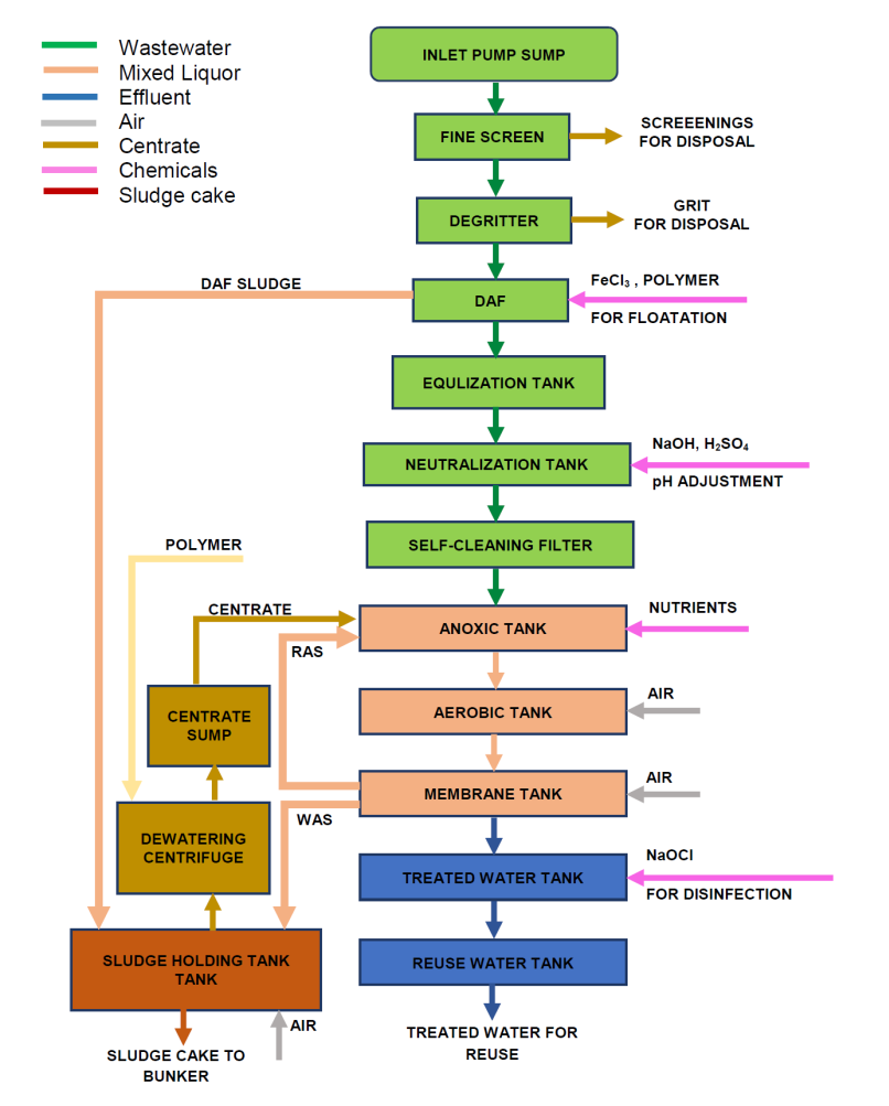
Figure 4‑1 Block flow diagram- Process Overview
IWMF1_02-531_231_000001_1, IWMF1_02-531_231_000002_1, IWMF1_02-531_231_000003_1 & IWMF1_02-531_231_000004_1 may be referred for detail process flow diagram (PFD) of the proposed WWTP.
All WWTP treatment basins and areas of odour emission will be maintained under negative pressure and odour will be extracted for treatment by incineration in furnace.
4.2 Pre-treatment Works Systems and EquipmentAll wastewaters from sources of Table 3‑1 are transferred to the influent sump pit. Then, the influent from sump pit is pumped to the fine screen (Figure 4‑2) channel by means of submersible pump (Figure 4‑3) for removal of debris. The debris is compacted further to remove moisture before it is transferred to concealed containers. The screened effluent passes to the vortex degritters (Figure 4‑4) where grits are airlifted to grit classifiers and degritted wastewater passes to the dissolved air floatation (DAF) units. The grit is separated in grit classifier and transferred into a concealed container for disposal. The clarified wash water is return to the mainstream at pre-treatment works for treatment
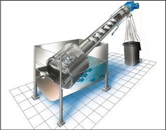
Figure 4‑2 Fine screens
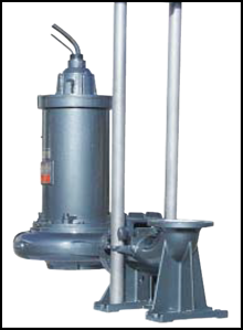
Figure 4‑3 Sump pumps
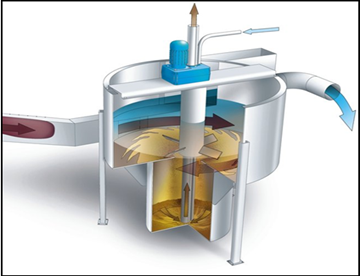
Figure 4‑4 Vortex Degritters
The DAF (Figure 4‑5) units are introduced to remove suspended solids, oil and grease from the wastewater and protect the downstream membrane bioreactor process. The scum / sludge removed from the DAF is transferred to the sludge holding tank for further treatment together with waste activated sludge from MBR.
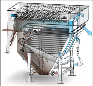
Figure 4‑5 Dissolved Air Floatation Unit
In order to enhance the floatation process, provisions are made for injection of coagulants such as FeCl3 and polymeric flocculants. The DAF recirculation pumps are designed to provide up to a maximum of 50% recirculation flows. The air saturated recycled water from saturation vessels are introduced via diffusers at the inlet of the floatation basin of DAF to facilitate maximum efficiency.
The clarified wastewater is transferred to an equalization tank by gravity. The purpose of the equalization tank is to consolidate, stabilise and equalise the pollutant levels of the incoming wastewater. It also attenuates abrupt fluctuations in wastewater flows and serves as a control point ensuring the constant flow rate of wastewater through the secondary biological treatment works. It also serves as a recycle point for any off-spec treated effluent tank.
After equalization, the wastewater is pumped to the pH neutralization basins for adjusting wastewater pH to approximately 7. Sodium hydroxide and sulphuric acid dosing system are used for pH adjustment. The pH neutralization tank is compartmentalised and equipped with top-mounted mixers. The neutralised wastewater from the break tank compartment is closed coupled with transfer pumps.
Self-cleaning filters (Figure 4‑6) are installed on the discharge piping of transfer pumps to remove finer debris that are harmful to the downstream membranes. All pre-treatment systems are designed for 100% duty / 100% standby configuration.
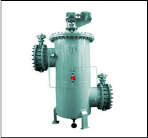
Figure 4‑6 Self-cleaning filters
Odours from fine screen, degritters, the skips, DAF, equalization tank and pH neutralization tanks are extracted and transferred to the WTE bunker for use as combustion air. PFD drawings IWMF1_02-531_231_000001_1 to IWMF1_02-531_231_000004_1 may be referred for further detail of pre-treatment works.
4.3 Secondary Treatment SystemsThe heart of the secondary treatment process is Anoxic - Oxic (AO) MBR process (Figure 4‑7). AO process is chosen due to significant nitrogenous concentrations usually found in leachate and sewage. Provision for return activated sludge (RAS) ratio of 800-900% is made in order to provide adequate flexibility for recycling nitrates to the anoxic compartments when high nitrogen concentrations are apparent in the wastewater. Also, higher RAS rates enable to keep the mixed liquor in tanks to be more consistent and helps maximise bioreactor solids retention time (SRT) without exceeding the membrane tank threshold mixed liquor concentration.
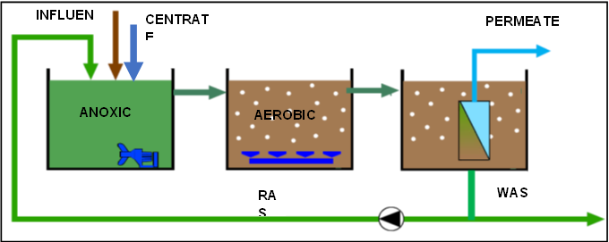
Figure 4‑7 Membrane Bioreactor
The additional provisions for pH adjustment is provided at the influent flow splitter to ensure that the mixed liquor (RAS, influent and centrate) is within the required limits for biological treatment. Also, provision for nutrient dosage are made in the first anoxic compartment to supplement any N or P shortage in the influent.
The bioreactor consists of two streams: A and B each capable of treating 50% of the plant capacity. Each bioreactor stream has 4 equal compartments. In each of the first two compartments, two submersible mixers (Figure 4‑8) are installed. The mixers provide a homogenous mixture of the mixed liquor with the incoming substrate, RAS and centrate steams.
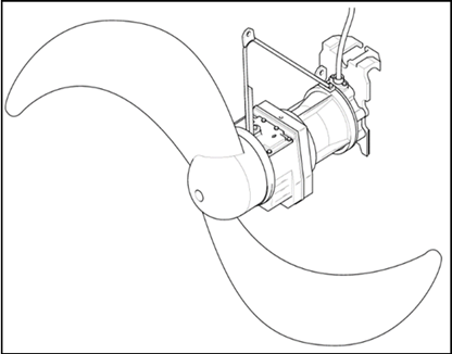
Figure 4‑8 Submersible mixers
The dissolve oxygen in the final compartment will be maintained to meet the effluent ammonium-nitrogen standards. The second, third and fourth compartments are installed with fine bubble diffused aeration system (Figure 4‑9) to maintain adequate aerobic solids retention time during low ambient temperature conditions.
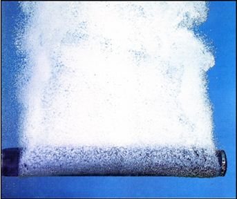
Figure 4‑9 Fine bubble aeration
Centrifugal blowers are selected based on their following advantages over the roots blowers:
(i) Variable flow with turndown to 45% or less at constant speed;
(ii) Low operating costs due to exceptional efficiency over the entire turndown range;
(iii) Low noise level with no pressure pulsation means there is less need for discharge silencer equipment;
(iv) Long service life with minimum maintenance;
(v) Accurate control even under fluctuating conditions;
(vi) Surge-free operation;
(vii) Maximum flexibility; and
(viii) Simplified control and instrumentation
Three centrifugal aeration blowers (2 duty, 1 standby) (Figure 4‑10) supply air to the diffused aeration system of the two bioreactor streams.
4.3.1 Aeration assembly and aeration control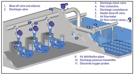
Figure 4‑10 Aeration blower assembly
A typical complete aeration system consists of compressor system; blow-off valve and silencer; discharge valve; discharge check valve; flex connectors; discharge cone/silencer; header blow-off valve; air flow control valves; air flow meters; discharge pressure transmitter; dissolved oxygen probes; and master control panel.
The electrically operated blow-off valve with silencer is open when the compressor is off-line, and closed after start-up. This ensures unloaded start-up and brings the compressor on-line gently. It is controlled from the local control panel (LCP). This electrically operated valve is used to isolate each off-line compressor. It opens automatically during start-up. It is controlled from the LCP. Discharge check valve is used to prevent reverse air flow while the compressor is off-line and is important for smooth start-up. It gets gradually pushed open as the air compressor comes on-line and builds up pressure.
Inlet and discharge flex connectors keep external loads from affecting the compressor casing. The cone diffuser reduces the air velocity and recovers up to 90% of the dynamic pressure head. When configured as a silencer, the noise level in the discharge pipe is also reduced remarkably. A header blow-off valve makes start-up and operation easier and helps avoid start-up surge effects. Overall system surge can be virtually eliminated by using an appropriate algorithm in the master control panel (MCP). Modulating air flow control valves must be sized to operate within a range of approximately 2080% open. Air flow meters that feature minimal pressure loss are used to control the air flow to each aerated zone. The pressure transmitter is mounted in the header to measure the discharge pressure. The difference between this value and the set point is used as the basis for adjusting the online compressor volume. DO probes are mounted in the aeration tanks to measure the dissolved oxygen. The difference between this value and the set point is used as the basis for adjusting the airflow control valve.
The master control panel (MCP) provides overall control and monitoring of an entire installation remotely, if required. The MCP controls the entire system of compressors, air header blow-off valves, air flow control valves, flow meters and dissolved oxygen sensors in one highly efficient, integrated system. The MCP is the heart of an automatically operated aeration system and uses job-specific, individually customised software for the three major control loops that optimise performance and results.
The functions of MCP are:
(i) air header pressure control regulates the online compressor volume based on an air header set point;
(ii) dissolved oxygen control fine-tunes the air flow, thus feeding the appropriate volume of air to each aeration cell; and
(iii) most open valve control maintains the air flow control valves in their most open position, ensuring the lowest overall system pressure.
Positive displacement blowers (Figure 4‑11) will be used for membrane skid aeration and sludge tank aeration, as these aeration requirements are significantly smaller than those of the bioreactor.
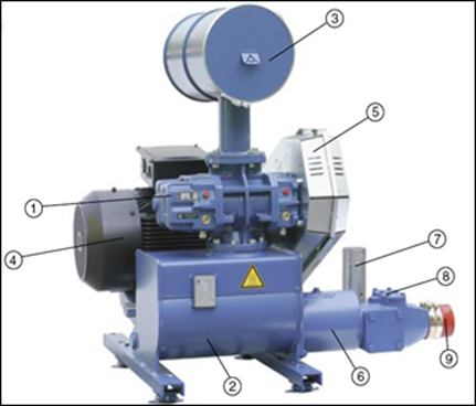
Figure 4‑11 Membrane blowers
The return activated sludge (RAS) pumps (Figure 4‑12) return activate sludge to the anoxic compartments while waste activate sludge pumps waste excess sludge to the sludge holding tank. PFD drawings IWMF1_02-531_231_000001_1 to IWMF1_02-531_231_000004_1 may be referred for further detail of secondary biological treatment works. All bioreactor tanks are covered and odour is extracted and transferred to the WTE bunker for use as combustion air in incineration lines.
Figure 4‑12 RAS Pumps
4.3.2 Membrane FiltrationBoth submerged and crossflow configurations (Figure 4‑13) have been considered in the selection of membrane configuration for MBR and both are found suitable for the proposed bioreactor configuration.
If a submerged configuration is selected in the final design, the mixed liquor from the last aerobic compartments will proceed by gravity into common channel and penstocks at the membrane tank inlet distribute the mixed liquor into the membrane filtration tanks in operation. Mixed liquor will overflow a weir at the end of each of the membrane filtration basin. Mixed liquor overflowing the membrane filtration basins will enter the deoxygenation zone and will be pumped back to the main bioreactor at a flow rate to ensure that the MLSS in the membrane filtration basins do not exceed threshold levels and adequate nitrates are recycled for denitrification. Permeate pump control and plant demand will be based on a combination of influent flow measurement and a level set point established in the bioreactor or elsewhere.

Figure 4‑13 Submerged and crossflow configurations
Whereas if a crossflow configuration is selected in the final design stage, the mixed liquor from the last aerobic compartments will be pumped in excess of the required permeate flow to the crossflow membrane modules and the permeate flow to the treated effluent tank will be controlled with a control valve based on feedback of permeate flow measurement. The permeate control will be based on a combination of influent flow measurement and a level set point established in the bioreactor or elsewhere. The excess mixed liquor from module is often returned to the RAS splitter. Also, WAS to sludge tank may be made from the RAS stream. Additional mixed liquor pumps may be often required to supplement additional recycles for denitrification.
4.3.2.1 Membrane FiltrationNormally, the membranes will be aerated and the aeration requirements vary among the membrane suppliers and the configuration used.
Cleaning is necessary to ensure a smooth operation of membrane modules and can be carried out quickly, easily, and automatically. Usually a multi-level approach is used to maintain membrane performance in every MBR system. The cleaning systems usually incorporate automated processes such as relaxation, backpulsing, maintenance cleaning and recovery cleaning. The cleaning methodology often depends on the membrane type and configuration used and often can be optimised to reduce the frequency of chemical cleaning based on site specific conditions and wastewater characteristics.
During normal operation, the MBR system is operated with a repeated filtration cycle, which consists of a production period (permeation) followed by a relaxation or backpulse period. Some MBR systems have the capability to operate in either relaxation or backpulse modes. Under normal conditions the system is operated in relaxation mode, whereas during start-up or under conditions of poor sludge filterability the system can be operated in backpulse mode. Details of the filtration cycle with relaxation and backpulse depend on the wastewater characteristics.
The membrane filtration system, including membranes, headers and mechanical equipment is sized to produce the design net flow rates under all operating scenarios.
While operating in relax mode in a submerged configuration, the permeate pump for each train may be stopped sequentially for a short period of time (typically 10 15 %) of every filtration duration to allow air scouring of the membrane without permeation. No chemical or permeate may be used during relaxation mode.
Under certain fouling conditions or when experiencing poor sludge characteristics, the ability to backpulse is essential to maintain membranes clean membrane and extend the membrane life. This feature allows for flexible and reliable system performance during unexpected influent or process operating scenarios. Applying the backpulse cleaning option is one of the simplest methods to ensure that submerged membranes retain optimum permeability throughout all operating conditions.
Backpulsing involves reversing the flow through the membranes to slightly expand the membrane pores and dislodge any particles that may have adhered to the membrane fibre surface. The permeate to be used for backpulsing will be taken from the treated water tank. When operating in Backpulse mode the system backpulses for typically 0-15% of the filtration period. Backpulse operation is usually made without the use of or mild dosages of chemicals.
4.3.2.2 Membrane CleaningIn addition to the normal filtration cycle, regular chemical cleaning is essential to maintain the performance of the membrane. O&M philosophy is to always maintain the membrane in a state of readiness to effectively handle flow fluctuations when they occur. This is achieved by using automatic in-situ maintenance cleans as described below.
Sodium hypochlorite is used to oxidise organic foulants and citric acid to remove inorganic scaling. The maintenance cleaning procedure incorporates the following features:
(i) Fully automated and the frequency may be set by the operator as recommended by supplier;
(ii) Performed without draining the membrane tank for submerged configuration;
(iii) Easily achieved in crossflow configuration by isolation of skid or rack; and
(iv) Duration of such cleaning may vary from supplier to supplier and usully doesnot exceed an an hour
Based on the site specific requirements, cleaning procedures may be modified to obtain effective cleaning and maximise chemical savings.
Recovery cleaning is required to restore the permeability of the membrane once the membrane becomes fouled. The recovery cleaning procedure consists of a chemical backpulse sequence, followed by a chemical soak period. The cleaning chemical concentrations typically used to soak the membranes are 1,000 -10,000 mg/L sodium hypochlorite (NaOCl) for the removal of organic foulants and 2,000 -10,000 mg/L citric acid for the removal of inorganic foulants. The maintenance and recovery cleaning concentrations will be adjusted based on membrane performance and wastewater characteristics.
Key features of the recovery cleaning procedure are:
(i) Fully automated and initiated by the operator;
(ii) Cleans all membrane of a skid of a train at the same time;
(iii) Recommended twice per annum
(iv) Requires moderate chemical concentration
4.4 Effluent DisinfectionPermeate pumps will draw permeate from the membrane skids and transfer it into the treated water tank where sodium hypochlorite is dosed for disinfection of treated effluent. The design contact time is ≥ 30 mins so that oxidation of residual organics and any chloramination of residual ammonia is completed in treated effluent tank. The chlorine dosage is determined such that the treated effluent leaving the tank has a total chlorine concentration of Table 3‑6. The tank structure is designed to ensure spiral flow and avoid short circuiting of effluent (Figure 4‑14).
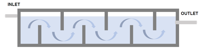
Figure 4‑14 Chlorine contact treated effluent tank
The treated effluent is transferred to two reuse water tanks of 300 m3 each. The effluent tank are epoxy coated bolted or weld carbon steel tanks with external weather and corrosion resistant painting and internal FRP or HDPE coating. These tanks will be sited on a concrete foundation (Figure 4‑15).
There is a continuous demand of reuse water and additional treated effluent can be stored in the Reuse Water Tanks. There is also 600m3 storage of influent in equalisation tank which is sufficiently designed to receive all anticipated flow fluctuations. Hence, the possibility of treated effluent overflow from the two Reuse Water Tanks is minimal.
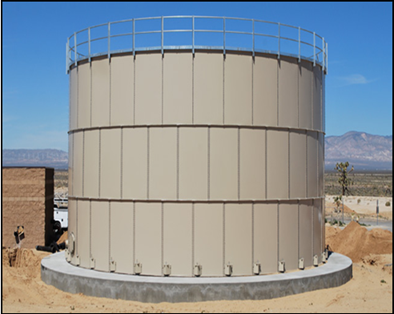
Figure 4‑15 Treated effluent storage tank
4.5 Sludge Treatment SystemsThe sludge in the sludge holding tank are mixed and kept under aerobic condition with coarse bubble aeration system prior to dewatering by centrifuge decanters. The Sludge from the sludge holding tank will be fed to the centrifuge decanters by means of progressive cavity pumps (Figure 4‑16). The sludge feed is premixed with polymer before it is introduced into the centrifuge decanters.
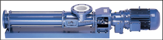
Figure 4‑16 Progressive cavity pumps
There are two options considered for polymer source: either a polymer preparation and dilution system that use dry polymer pellets (Figure 4‑17) or a dilution system for a commercial 50% polymer solution. Final selection will be made based on lifecycle cost consideration.
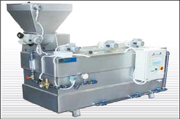
Figure 4‑17 Polymer preparation system
The sludge is mechanically dewatered to minimum 20 % DS by decanter centrifuges (Figure 4‑18). Dewatered sludge is conveyed by screw conveyors to the refuse bunker. Centrate from the decanter centrifuge is led to the centrate sump by gravity. Then, the centrate is returned to the inlet of the bioreactor by means of submersible pumps (Figure 4‑19). The special pedestal is mounted on the sump floor during construction of the pump station and is then connected to the discharge line. A guide rail connects the pedestal to the pipe retainer located at the sump opening. The system ensures quick installation and economical maintenance of the pump.
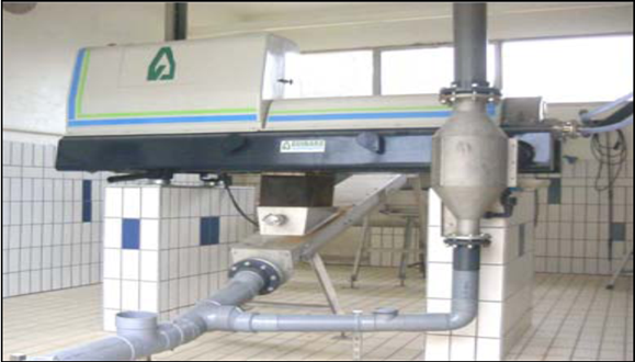
Figure 4‑18 Dewatering Centrifuge
The decanter centrifuge is composed of a rotating assembly, driven by electrical motors, supported by two pillow blocks on a base frame. The rotating assembly includes a cylindrical and conical bowl, a scroll conveyor and a gear box, which creates the differential speed between the scroll conveyor and the bowl. The decanter is designed for a continuous attention-free operation, through a specific electronic system. The shutdown of the decanter can be programmed outside of the operators working hours on site and 24 hours continuous operation too is possible, if required.
The inline design of decanter centrifuges reduces the floor-space requirements to a minimum. Its isostatic design decreases vibrations and noise level. The decanter resting on vibrations shock isolators is typically installed on concrete supports. The feed must be regular and homogenous by an adjustable flow rate positive displacement volumetric pump. An industrial water entry for decanter washing must be available (very low washwater consumption and only during the equipment shutdown).
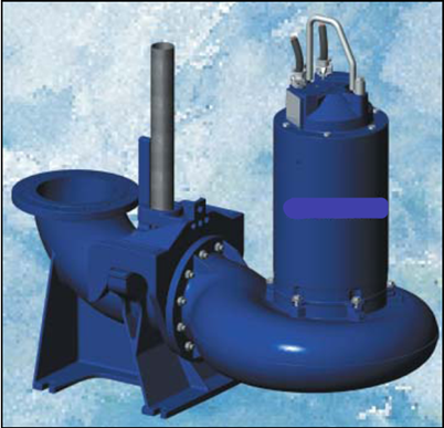
Figure 4‑19 Centrate pump
The open solids discharge casing facilitates the installation of any evacuation system. The installation of an inclined shaftless screw conveyor with a bottom drain hole for the gravity discharge of the slops at the beginning and the end of each operating cycle is preferred. The de-aerator captures and separates the air dragged with the centrate discharge and allow for its easy evacuation to the outside into the sump by gravity. Odour is extracted from centrifuge hoods, conveyor and skips and transferred for further treatment.
The power and control panel of the decanter centrifuge will be installed in the MCC room with fresh air ventilation, without any contact with the dewatering room, in order to prevent electrical wires and electronic cards corrosion. A local control panel can be installed on a wall near by the decanter if required.
4.6 Chemical Dosing SystemsAll chemical preparation and dosing facilities will be fully automated. All operation data, status and alarms of the systems shall be reported to the SCADA/ DCS system to facilitate control and monitoring.
Design of the dosing system take into considerations to minimize operator exposures to the chemicals and operation of the chemical systems will be designed as automated as possible. All chemical storage tanks and dosing tanks will be equipped with overfill protection. The chemical dosing tanks for all the chemicals and operating supplies used by the Wastewater Treatment Plant are designed for a storage capacity of at least 5 days.
Provisions for bunds or catch basins are made in layout (Figure 4‑20) for the siting of chemical dosing systems, chemical storage and chemical dosing tanks to prevent water pollution. The concrete tanks for storage of chemicals shall be lined with appropriate materials for chemical and mechanical (if required) protection.
Rinsing connections and connections used to perform conservation measures will be provided for all auxiliary equipment and units subjected to chemicals and suspensions.
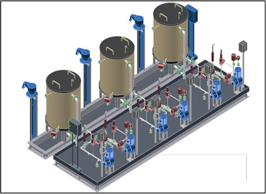
Figure 4‑20 Typical chemical dosing system layout
Also, chemical handling area will be provided with eyewashes, drench showers and any other necessary emergency safety equipment to cater for any emergency situations.
Emergency eyewash fountains and drench showers will be provided as a safety precaution for the personnel working in all areas associated with delivery, storage and dosing of chemicals. Fountains and showers will be fed with potable water and drained to a dedicated connection to the floor drain or drain sump. All showers and fountains will be fitted with alarm to indicate usage and report to usage and the place of the usage to the control system.
Chemical storage tank for preparation of chemical solution or liquid chemicals shall be made of glass fibre reinforced plastic (GRP) or other materials with the required corrosion resistant properties (Figure 4‑21).
Resin used for the GRP tanks shall be of type that provides the required corrosion resistant properties for the stored chemicals. Resin type including all the relevant technical data shall be provided in the design submissions.
All concrete tanks for storage of chemicals shall be lined with appropriate materials for chemical and mechanical (if required) protection.
Double containment pipes will be used for those pipelines carrying dangerous chemicals of stock concentration and also corrosive/ hazardous liquid chemicals which are installed at outside bund areas. They are the high level chemical pipelines and also corrosive/ hazardous liquid chemical pipelines.
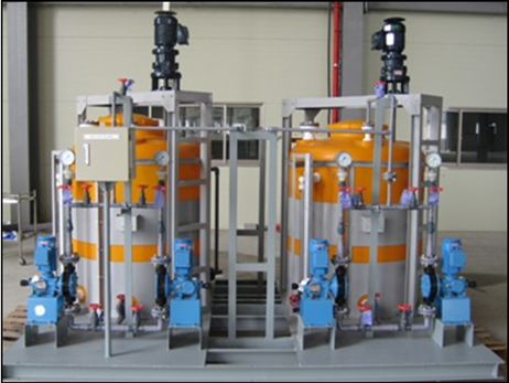
Figure 4‑21 Chemical dosing skids
4.7 Emergency overflows and Emergency ResponseAny accidental emergency overflows from all stages of WWTP will be drained to a drainage sump and submersible sump pumps will transfer these to emergency overflow tank located adjacent to equalisation tank. Where the overflows are from treatment tanks of WWTP, these will be return to the plants equalisation tank for subsequent treatment.
The emergency overflow tank is to provide a basis for accidental overflows from WWTP due to tripping of pumps, or failure of instrumentation and such events can be readily detected from the DCS and corrective actions may be made timely.
The capacity of Emergency Overflow Tank is 150m3 which allows response time of 6 hours with average flow and 4 hours during peak flow. The detail engineering of WWTP will ensure that corrective actions or emergency responses for WWTP will be made within this duration.
During emergency situation such as electricity shortage, the operation of WWTP will not be affected because the IWMF1 is designed such that the in-house power consumption will be served before any excess electricity is exported. During plant breakdown, waste water generation will be reduced significantly as the major plant activities including waste incineration and truck washing will stop operation and hence will not generate wastewater. During that situation, the 150m3 Emergency Overflow Tank can have retention time up to 42 hours. In an unlikely event when there is prolonged plant breakdown, the wastewater will be removed from the IWMF1 Facility by tanker service for treatment at other facility.
4.8 Lifting EquipmentThe preliminary treatment works and bioreactor equipment will be serviced using pillar jib cranes with a safe working load (SWL) 0.5 tonnes while for the maintenance of the dry-mounted pumps, membrane skids and blowers traveling cranes will be provided (Figure 4‑22).
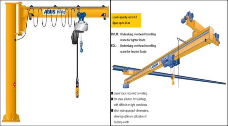
Figure 4‑22 Lifting equipment
5 PRELIMINARY DESIGN
The WWTP is design to treat average and peak flows of 598.15 and 897.22 m3/d, respectively. Of the average flow treated by WWTP, approximately 60% (360 m3/d) of wastewater treated are high organic strength.
5.1 Pre-treatmentThe major process treatment systems of the proposed WWTP are: the Inlet Pump Station; Fine Screen; Vortex Degritter, Dissolved Air Floatation, Equalisation Basin and Neutralization Unit; and Self-cleaning Filters.
Table 5‑1 illustrates the preliminary design parameters and calculation for these treatment systems.
Table 5‑1 Preliminary pre-treatment works process design
|
Item |
Description |
Unit |
Input |
|
Inlet Pump Sump |
|||
|
1. |
Type |
-- |
Rectangular RC Tank with Epoxy coated |
|
2. |
Quantity (duty) |
-- |
1 |
|
3. |
Effective tank volume |
m3 |
105 |
|
4. |
Dimensions |
-- |
7.0 m (L) x 3.0 m (W) x 6.0 m(H) |
|
Sump Pump |
|||
|
1. |
Type and applicable standards |
-- |
Centrifugal, Submersible, Cutter Impeller Pump |
|
2. |
Quantity (duty/standby) |
-- / -- |
1 / 1 |
|
3. |
Unit flow rate |
m3 / d |
900 |
|
4. |
Pump head |
m |
12 |
|
5. |
Material |
-- / -- |
Duplex SS |
|
6. |
Power rating |
V |
380V / 3ph / 50 Hz |
|
7. |
Accessories |
-- |
Sliding bar & bracket, Guide rail holder, Electric Motor with lifting Chain & Cable |
|
Fine Screen |
|||
|
1. |
Type and applicable standards |
-- |
Motorized Fine Screen |
|
2. |
Quantity (duty/standby) |
-- / -- |
1 / 1 |
|
3. |
Unit flow rate |
m3 / d |
900 |
|
4. |
Material (Casing/Shaft/Impeller) |
-- / -- |
SS316Ti or Equal |
|
5. |
Slot/ Aperture opening |
mm |
3 |
|
6. |
Screening removal rate |
kg/d |
1,000 |
|
Fine Screen |
|||
|
7. |
Power Supply |
|
380V / 3ph / 50 Hz |
|
Grit Separator |
|||
|
1. |
Type |
-- |
Vortex |
|
2. |
Quantity (duty/standby) |
-- / -- |
1 / 1 |
|
3. |
Unit flow rate |
m3 / d |
900 |
|
4. |
Grit removal rate |
kg/d |
2,000 |
|
Agitator |
|||
|
1. |
Type |
-- |
Vertical Propeller Type |
|
2. |
Quantity |
pcs |
2 (One per girt separator) |
|
3. |
Power supply |
V |
380V / 3ph / 50 Hz |
|
4. |
Material |
-- |
SS316Ti or Equal |
|
Grit Removal Pump |
|||
|
1. |
Type |
-- |
Airlift pump |
|
2. |
Quantity |
pcs |
2 (One per girt separator) |
|
Grit Classifier |
|||
|
1. |
Quantity (duty/standby) |
-- / -- |
1 / 1 |
|
2. |
Capacity |
l/s |
8.0 |
|
3. |
Power supply |
V |
380V / 3ph / 50 Hz |
|
4. |
Material |
-- |
SS316L or Equal |
|
Grit Skip |
|||
|
1. |
Type |
-- |
Rectangular CS + Epoxy Tank |
|
2. |
Quantity (duty/standby) |
-- / -- |
1 / 1 |
|
3. |
Skip dimensions |
-- |
1.0 m (L) x 0.5 m (W) x 1.0 m(H) |
|
Dissolved Air Floatation (DAF) Tank |
|||
|
1. |
Type |
-- |
Rectangular RC Tank with Epoxy coated |
|
2. |
Quantity (duty/standby) |
-- / -- |
1 / 1 |
|
3. |
Capacity |
m3/d |
900 |
|
DAF Surface Scraper |
|||
|
1. |
Type |
-- |
Surface Scraper |
|
DAF Surface Scraper |
|||
|
2. |
Quantity |
pcs |
2 (one for each DAF tank) |
|
3. |
Material of construction |
-- |
SS304 or Equal |
|
4. |
Power Supply |
V |
380V / 3ph / 50 Hz |
|
DAF Recirculation Pump |
|||
|
1. |
Type and applicable standards |
-- |
Centrifugal, dry mounted |
|
2. |
Quantity (duty/standby) |
-- / -- |
1 / 1 |
|
3. |
Unit flow rate |
m3 / d |
480 |
|
4. |
Material |
-- / -- |
Duplex SS |
|
5. |
Power supply |
V |
380V / 3ph / 50 Hz |
|
DAF Sludge Transfer Pump |
|||
|
1. |
Type and applicable standards |
-- |
Centrifugal, dry mounted |
|
2. |
Quantity (duty/standby) |
-- / -- |
1 / 1 |
|
3. |
Unit flow rate |
m3 / d |
28 |
|
4. |
Pump head |
bar |
2.0 |
|
5. |
Material |
-- |
Duplex SS |
|
6. |
Power supply |
kW |
380V / 3ph / 50 Hz |
|
Equalization Tank |
|||
|
1. |
Type |
-- |
Rectangular RC Tank with Epoxy coated |
|
2. |
Capacity |
m3 |
600 |
|
3. |
Tank dimensions |
-- |
13.0 m (L) x 7.0 m (W) x 7.5 m(H) |
|
Emergency overflow tank |
|||
|
1. |
Type |
-- |
Rectangular RC Tank with Epoxy coated |
|
2. |
Capacity |
m3 |
150 |
|
3. |
Tank dimensions |
-- |
7.0 m (L) x 3.0 m (W) x 7.5 m(H) |
|
Equalization Tank Mixing Pumps |
|||
|
1. |
Type and applicable standards |
-- |
Centrifugal |
|
2. |
Quantity (duty/standby) |
-- / -- |
1 / 1 |
|
3. |
Unit flow rate |
m3 / d |
625 |
|
4. |
Pump head |
m |
10 |
|
Equalization Tank Mixing Pumps |
|||
|
5. |
Material |
-- / -- |
Duplex SS |
|
6. |
Power supply |
V |
380V / 3ph / 50 Hz |
|
Equalization Tank Transfer Pumps |
|||
|
1. |
Type and applicable standards |
-- |
Centrifugal, Submersible |
|
2. |
Quantity (duty/standby) |
-- / -- |
1 / 1 |
|
3. |
Unit flow rate |
m3 / d |
600 |
|
4. |
Pump head |
m |
15 |
|
5. |
Material |
-- / -- |
Duplex SS |
|
6. |
Power supply |
V |
380V / 3ph / 50 Hz |
|
7. |
Accessories |
|
Sliding bar & bracket, Guide rail holder, Electric Motor with lifting Chain & Cable |
|
Neutralization Tanks |
|||
|
1. |
Type |
-- |
Rectangular RC Tank with Epoxy coated |
|
2. |
Each Tank Size |
-- |
2 Nos. x 2.5 m(L) x 2.5 m(W) x 2.5 m(H) |
|
Neutralization Tank Agitator 3 Nos. x 1.0 m(L) x 2.2 m(W) x 4.0 m(H) |
|||
|
1. |
Type and applicable standards |
-- |
Top Entry Vertical Single Stage Impeller |
|
2. |
Quantity (duty/standby) |
pcs |
2 (One per tank) |
|
3. |
Power supply |
V |
380V / 3ph / 50 Hz |
|
MBR Feedwater Pump |
|||
|
1. |
Type and applicable standards |
-- |
Horizontal Centrifugal Pump |
|
2. |
Quantity (duty/standby) |
-- / -- |
1 / 1 |
|
3. |
Capacity |
m3 / d |
600 |
|
4. |
Pressure |
bar |
2.5 |
|
5. |
Material |
-- |
Duplex SS |
|
6. |
Power supply |
V |
380V / 3ph / 50 Hz |
|
7. |
Pump Material (Casing/ Impeller/ Shaft) |
-- |
SS316L/ SS316L/ SS316L |
|
Self-Cleaning Filter |
|||
|
1. |
Type and applicable standards |
-- |
Vertical cylindrical |
|
2. |
Quantity (duty/standby) |
-- / -- |
1 / 1 |
|
3. |
Capacity |
m3 / d |
600 |
|
Self-Cleaning Filter |
|||
|
4. |
Pressure (Design / Operation ) |
|
6.0 / 3.0 |
|
5. |
Aperture size |
mm |
1.0 |
|
6. |
Material |
-- |
Housing SS316L/ Screen SS316L/ Shaft & Cleaning Arm SS316L
|
5.2 Secondary Treatment
Total design loading to the bioreactor streams A & B is shown in Table 5‑2. Simulation is made with GPS-X and results of simulation are presented in drawing IWMF_02-533_231_000001_1 MASS BALANCE. The same is presented in Figure 5‑1 and Table 5‑3.
Table 5‑2 Design mass loading rates of biological treatment works
|
Item |
Parameters |
Unit |
Design Mass Loading Rates |
|
1. |
BOD5 |
kg O2/d |
15,671.53 |
|
COD |
kg O2/d |
17,765.06 |
|
|
TKN |
kg N/d |
753.67 |
|
|
NH4+-N |
kg N/d |
593.36 |
|
|
TSS |
kg TSS/d |
2,021.75 |
|
|
VSS |
kg VSS/d |
1,519.30 |
|
|
7. |
TP |
kg P/d |
58.51 |
|
8. |
TDS |
kg TDS/d |
8,667.88 |
|
9. |
Sulfate (SO42-) |
kg S/d |
107.71 |
|
10. |
Alkalinity |
kg CaCO3/d |
1,083.25 |
|
Chloride (Cl-) |
kg Cl-/d |
858.38 |
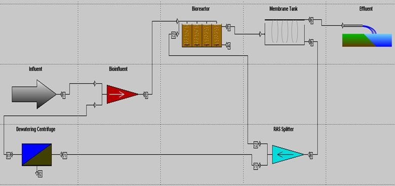
Figure 5‑1 WWTP Simplified Model in GPS-X
Table 5‑3 Mass balance simplified MBR of WWTP
|
Description |
Unit |
Influent |
Centrate |
Bioinfluent |
Membrane Tank Feed |
Effluent |
WAS |
RAS |
Sludge Cake |
|
Line No |
|
1 |
81 |
2 |
3 |
5 |
71 |
72 |
82 |
|
Flow |
m3/d |
598.2 |
403.0 |
1,001.2 |
6,551.2 |
583.2 |
418.0 |
5,550.0 |
15.0 |
|
TSS |
kg/d |
2,021.7 |
132.6 |
2,154.3 |
56,012.3 |
0.5 |
3,925.0 |
52,086.8 |
3,792.4 |
|
VSS |
kg/d |
1,519.3 |
114.9 |
1,634.2 |
48,544.0 |
0.4 |
3,398.3 |
45,145.2 |
3,283.5 |
|
BOD5 |
kg/d |
15,671.5 |
60.0 |
15,731.6 |
25,221.9 |
0.9 |
1,764.0 |
23,457.0 |
1,703.9 |
|
COD |
kg/d |
17,765.1 |
697.2 |
18,462.2 |
80,579.1 |
763.9 |
5,559.4 |
74,255.8 |
4,862.2 |
|
TKN |
kg/d |
753.7 |
13.1 |
766.7 |
5,313.0 |
0.8 |
372.0 |
4,940.2 |
359.0 |
|
SCOD |
kg/d |
15,611.7 |
527.9 |
16,139.6 |
8,582.0 |
763.9 |
547.6 |
7,270.5 |
19.7 |
|
NH4-N |
kg/d |
593.4 |
0.2 |
593.6 |
3.2 |
0.3 |
0.2 |
2.7 |
0.0 |
|
NO3-N |
kg/d |
1.2 |
9.9 |
11.1 |
161.2 |
14.3 |
10.3 |
136.5 |
0.4 |
|
TN |
kg/d |
754.9 |
23.0 |
777.8 |
5,474.1 |
15.2 |
382.3 |
5,076.7 |
359.3 |
|
VSS/TSS |
gVSS/gTSS |
0.75 |
0.87 |
0.76 |
0.87 |
0.87 |
0.87 |
0.87 |
0.87 |
|
TSS |
mg/L |
3,380.0 |
329.0 |
2,151.9 |
8,550.0 |
0.9 |
9,390.0 |
9,385.0 |
252,828.9 |
|
VSS |
mg/L |
2,540.0 |
285.0 |
1,632.3 |
7,410.0 |
0.7 |
8,130.0 |
8,134.3 |
218,899.0 |
|
BOD5 |
mgO2/L |
26,200.0 |
149.0 |
15,713.5 |
3,850.0 |
1.6 |
4,220.0 |
4,226.5 |
113,594.2 |
|
COD |
mgCOD/L |
29,700.0 |
1,730.0 |
18,441.0 |
12,300.0 |
1,310.0 |
13,300.0 |
13,379.4 |
324,147.3 |
|
TKN |
mgN/L |
1,260.0 |
32.4 |
765.8 |
811.0 |
1.4 |
890.0 |
890.1 |
23,930.9 |
|
SCOD |
mgCOD/L |
26,100.0 |
1,310.0 |
16,121.1 |
1,310.0 |
1,310.0 |
1,310.0 |
1,310.0 |
1,310.0 |
|
NH4-N |
mgN/L |
992.0 |
0.5 |
592.9 |
0.5 |
0.5 |
0.5 |
0.5 |
0.5 |
|
NO3-N |
mgN/L |
2.0 |
24.6 |
11.1 |
24.6 |
24.6 |
24.6 |
24.6 |
24.6 |
|
TN |
mgN/L |
1,262.0 |
57.0 |
776.9 |
835.6 |
26.0 |
914.6 |
914.7 |
23,955.5 |
Secondary treatment works major equipment comprises the biological tanks, anoxic tank mixers, aeration blowers, fine bubble diffused aeration, RAS pumps and WAS pumps. Table 5‑4 shows the preliminary equipment selection and sizing of secondary treatment works.
Table 5‑4 Preliminary secondary treatment process design
|
Item |
Description |
Unit |
Input |
|
Anoxic Tank 1 of Bioreactor Stream A & B |
|||
|
1. |
Type |
-- |
Rectangular RC Tank with Epoxy coated |
|
2. |
Quantity |
-- |
2 (1 for each bioreactor stream tank 1) |
|
3. |
Effective depth |
m |
8.25 |
|
4. |
Effective tank volume |
m3 |
907.5 |
|
5. |
Dimensions |
-- |
10.0 m (L) x 11.0 m (W) x 9.0 m(H) |
|
Anoxic Tank 1 of Bioreactor Stream A & B Submersible Mixer |
|||
|
1. |
Type and applicable standards |
-- |
Submersible Mixer |
|
2. |
Quantity |
-- |
Min 2 Nos. (1 for each bioreactor stream tank 1) |
|
3. |
Material |
-- |
Casing SS316L/ Shaft & Impeller SS316L |
|
4. |
Power Supply |
V |
380V / 3ph / 50 Hz |
|
5. |
Accessories |
-- |
Sliding bar & bracket, Guide rail holder, Electric Motor with lifting Chain & Cable |
|
Anoxic / Aerobic Tank 2 of Bioreactor Stream A & B |
|||
|
1. |
Type |
-- |
Rectangular RC Tank with Epoxy coated |
|
2. |
Quantity |
-- |
2 (1 for each bioreactor stream tank 2) |
|
3. |
Effective depth |
m |
8.15 |
|
4. |
Effective tank volume |
m3 |
896.5 |
|
5. |
Dimensions |
-- |
10.0 m (L) x 11.0 m (W) x 9.0 m(H) |
|
Anoxic / Aerobic Tank 2 of Bioreactor Stream A & B Submersible Mixer |
|||
|
1. |
Type and applicable standards |
-- |
Submersible Mixer |
|
2. |
Quantity |
-- |
Min 2 Nos. (1 for each bioreactor stream tank 1) |
|
3. |
Material |
-- |
Casing SS316L/ Shaft & Impeller SS316L |
|
4. |
Power Supply |
V |
380V / 3ph / 50 Hz |
|
5. |
Accessories |
-- |
Sliding bar & bracket, Guide rail holder, Electric Motor with lifting Chain & Cable
|
|
Aerobic Tank 3 of Bioreactor Stream A & B Submersible Mixer |
|||
|
1. |
Type |
-- |
Rectangular RC Tank with Epoxy coated |
|
2. |
Quantity |
-- |
2 (1 for each bioreactor stream tank 3) |
|
3. |
Effective depth |
m |
8.05 |
|
4. |
Effective tank volume |
m3 |
885.5 |
|
5. |
Dimensions |
-- |
10.0 m (L) x 11.0 m (W) x 9.0 m(H) |
|
Aerobic Tank 4 of Bioreactor Stream A & B
|
|||
|
1. |
Type |
-- |
Rectangular RC Tank with Epoxy coated |
|
2. |
Quantity |
-- |
2 (1 for each bioreactor stream tank 4) |
|
3. |
Effective depth |
m |
7.95 |
|
4. |
Effective tank volume |
m3 |
874.5 |
|
5. |
Dimensions |
-- |
10.0 m (L) x 11.0 m (W) x 9.0 m(H) |
|
Air Diffuser for Anoxic/ Aerobic Tank 2 of Bioreactor Stream A & B |
|||
|
1. |
Design air flow |
Sm3/h |
3,800 (each tank) |
|
2. |
Type of diffused aerator |
--- |
Tube / Disc |
|
3. |
Material |
-- |
EPDM |
|
4. |
Accessories |
-- |
Snappy saddle, Header-pipe, Sub-header pipe & Fitting c/w pipe support |
|
Air Diffuser for Aerobic Tank 3 of Bioreactor Stream A & B |
|||
|
1. |
Design air flow |
Sm3/h |
5,700 (each tank) |
|
2. |
Type of diffused aerator |
--- |
Tube / Disc |
|
3. |
Material |
-- |
EPDM |
|
4. |
Accessories |
-- |
Snappy saddle, Header-pipe, Sub-header pipe & Fitting c/w pipe support |
|
Air Diffuser for Aerobic Tank 4 of Bioreactor Stream A & B |
|||
|
1. |
Design air flow |
Sm3/h |
3,800 (each tank) |
|
2. |
Type of diffused aerator |
--- |
Microporous Fine Bubble Tube / Disc |
|
3. |
Material |
-- |
EPDM |
|
4. |
Accessories |
-- |
Snappy saddle, Header-pipe, Sub-header pipe & Fitting c/w pipe support |
|
|
|||
|
Aeration Blower for Bioreactor |
|||
|
1. |
Type |
-- |
Centrifugal |
|
2. |
Quantity (duty/standby) |
-- / -- |
2 / 1 |
|
3. |
Unit capacity |
Sm3/h |
7,600 |
|
4. |
Gauge pressure |
kPa |
925 |
|
5. |
Material |
-- |
Impeller SS304/ Volute Cast Iron Grade250/ Gear Box Cast Iron Grade250/ Shaft SS304 |
|
6. |
Power Supply |
V |
380V / 3ph / 50 Hz |
|
RAS Pumps |
|||
|
1. |
Type and applicable standards |
-- |
Centrifugal, Horizontal dry-mounted |
|
2. |
Quantity (duty/standby) |
-- / -- |
1 / 1 |
|
3. |
Unit flow rate |
m3 / d |
5550 |
|
4. |
Pump head |
m |
10 |
|
5. |
Material |
-- / -- |
Duplex SS |
|
6. |
Power Supply |
V |
380V / 3ph / 50 Hz |
|
WAS Pumps |
|||
|
1. |
Type and applicable standards |
-- |
Centrifugal, Horizontal dry-mounted |
|
2. |
Quantity (duty/standby) |
-- / -- |
1 / 1 |
|
3. |
Unit flow rate |
m3 / d |
504 |
|
4. |
Pump head |
m |
10 |
|
5. |
Material |
-- / -- |
Casting Cast-iron/ Impeller & Shaft SS316L |
|
6. |
Power Supply |
V |
380V / 3ph / 50 Hz |
The preliminary design on membrane filtration will be provided upon finalisation of the type of configuration between crossflow and submerged type.
5.3 Post TreatmentThe main disinfection process comprises baffled tank, treated water tank and treated water transfer pumps. The preliminary equipment selection and sizing are shown in Table 5‑5.
Table 5‑5 Preliminary disinfection and effluent reuse equipment sizing
|
Item |
Description |
Unit |
Input |
|
Baffled Disinfection Tank |
|||
|
1. |
Type |
-- |
Rectangular RC Tank with Baffles with Epoxy coated |
|
2. |
Quantity |
-- |
1 |
|
3. |
Tank dimensions |
-- |
7.7 m (L) x 2.5 m (W) x 2.0 m(H) |
|
Treated Water Tank |
|||
|
1. |
Type and applicable standards |
-- |
Rectangular RC Tank with Epoxy coated |
|
2. |
Quantity |
-- |
1 |
|
3. |
Tank dimensions |
-- |
5 m (L) x 2.5 m (W) x 4 m(H) |
|
Treated Water Transfer Pumps / Off-spec Water Transfer Pumps |
|||
|
1. |
Type and applicable standards |
-- |
Horizontal Centrifugal Pump |
|
2. |
Quantity (duty/standby) |
-- / -- |
1 / 1 |
|
3. |
Unit flow rate |
m3 / d |
600 |
|
4. |
Pump head |
m |
15 |
|
5. |
Material |
-- / -- |
Casing Cast iron/ Impeller SS304L/ Shaft SS304L |
|
6. |
Power Supply |
V |
380V / 3ph / 50 Hz |
|
Reuse Water Tank |
|||
|
1. |
Type and applicable standards |
-- |
Vertical Cylindrical Bolted Epoxy Coated (baked) Carbon Steel Tank |
|
2. |
Quantity |
-- |
2 |
|
3. |
Unit Capacity |
m3 |
300 |
|
4. |
Tank dimensions |
-- |
7.0 m (Dia.) x 8.3 m(H) |
|
Reuse Water Recirculation Pump |
|||
|
1. |
Type and applicable standards |
-- |
Horizontal Centrifugal Pump |
|
2. |
Quantity (duty/standby) |
-- / -- |
1 / 1 |
|
3. |
Unit flow rate |
m3 / d |
600 |
|
4. |
Pump head |
bar |
5 |
|
5. |
Material |
-- / -- |
Casing Cast iron/ Impeller SS304L/ Shaft SS304L |
|
6. |
Power Supply |
V |
380V / 3ph / 50 Hz |
The sludge treatment work major equipment comprises: sludge holding tank, centrifuge feed pumps, centrifuges, polymer dosing system and centrate pumps and sludge cake conveyors. The preliminary equipment selection and sizing are shown in Table 5‑6.
Table 5‑6 Preliminary sludge treatment equipment sizing
|
Item |
Description |
Unit |
Input |
|
Sludge Holding Tank |
|||
|
1. |
Type |
-- |
Rectangular RC Tank with Epoxy coated |
|
2. |
Quantity |
-- |
1 (Two compartments) |
|
3. |
Tank dimensions |
-- |
4.0 m (L) x 2.5 m (W) x 5.0 m(H) |
|
4. |
Tank mixing method |
|
Coarse Bubble Aeration |
|
Sludge Tank Blower |
|||
|
1. |
Type |
-- |
Rotary Lobe Blower |
|
2. |
Quantity (duty/standby) |
-- / -- |
1 / 1 |
|
3. |
Unit capacity |
Sm3/h |
850 |
|
4. |
Gauge pressure |
kPa |
450 |
|
5. |
Material |
-- |
Impeller Cast iron/ Volute Cast Iron / Gear Box Ductile Iron / Shaft Alloy SteelGear Box Cast Iron Grade250/ Shaft SS304 |
|
6. |
Power Supply |
V |
380V / 3ph / 50 Hz |
|
7. |
Accessories |
|
Silencer, PSV, Air filter, Expansion Joint, Pressure gauge |
|
Centrifuge Feed Pump |
|||
|
1. |
Type and applicable standards |
-- |
Progressive Cavity Pump |
|
2. |
Quantity (duty/standby) |
-- / -- |
3 / 2 |
|
3. |
Unit flow rate |
m3 / h |
35 |
|
4. |
Pump head |
bar |
3.0 |
|
5. |
Material |
-- / -- |
Stator CS with mould elastomer/ Rotor & Shaft SS316L |
|
6. |
Power Supply |
V |
380V / 3ph / 50 Hz |
|
Dewatering Centrifuge |
|||
|
1. |
Type and applicable standards |
-- |
Decanter Centrifuge |
|
2. |
Quantity (duty/standby) |
-- / -- |
1 / 1 |
|
Dewatering Centrifuge |
|||
|
3. |
Unit flow rate |
m3 / h |
35 |
|
4. |
Design Capacity |
kg TSS /h |
350 |
|
5. |
Operation hours |
h / d |
12 |
|
6. |
Material |
-- |
Bowl SS316L/ Scroll Duplex SS |
|
7. |
Power Supply |
V |
380V / 3ph / 50 Hz |
|
Centrate Sump |
|||
|
1. |
Type |
-- |
Rectangular RC Tank Epoxy coated |
|
2. |
Quantity |
-- |
1 |
|
3. |
Tank dimensions |
-- |
2.5 m (L) x 2.0 m (W) x 6.5 m(H) |
|
Centrate Pump |
|||
|
1. |
Type and applicable standards |
-- |
Centrifugal Submersible Pump |
|
2. |
Quantity (duty/standby) |
-- / -- |
1 / 1 |
|
3. |
Unit flow rate |
m3 / h |
35 |
|
4. |
Pump head |
m |
15 |
|
5. |
Material |
-- / -- |
Duplex SS |
|
6. |
Power Supply |
V |
380V / 3ph / 50 Hz |
|
7. |
Accessories |
|
Sliding bar & bracket, Guide rail holder, Electric Motor with lifting Chain & Cable |
5.5 Chemical dosing system
The chemical dosing system comprises Sodium Hypochlorite, Citric Acid, Sodium Hydroxide, Suphuric Acid, Ferric Chloride, Urea, Potasium Phosphate and polymer dosing systems. The preliminary equipment selection and sizing are shown in Table 5‑7.
Table 5‑7 Preliminary chemical dosing system equipment sizing
|
Item |
Description |
Unit |
Input |
|
NaOCl Storage Tank |
|||
|
1. |
Type |
-- |
Vertical Cylinder |
|
2. |
Quantity |
-- |
1 |
|
3. |
Tank dimensions |
-- |
1.2 m(Dia.) x 1.5 m(H) |
|
4. |
Capacity |
m3 |
1 |
|
NaOCl Storage Tank |
|||
|
5. |
Tank Material |
-- |
FRP |
|
6. |
Stock Concentration by weight |
% |
12 |
|
NaOCl Dosing Pump for CEB Cleaning |
|||
|
1. |
Type and applicable standards |
-- |
Solenoid Driven Diaphragm Metering |
|
2. |
Quantity (duty) |
-- / -- |
1 |
|
3. |
Unit flow rate |
L / h |
12 |
|
4. |
Pump head |
bar |
4.0 |
|
5. |
Material |
-- / -- |
PP/PTFE/ Ceramic |
|
6. |
Power Supply |
V |
380V / 3ph / 50 Hz |
|
7. |
Accessories |
|
Pressure Gauge, Calibration Column, PRV, Back Pressure Valve |
|
NaOCl Dosing Pump for CIP Cleaning |
|||
|
1. |
Type and applicable standards |
-- |
Solenoid Driven Diaphragm Metering |
|
2. |
Quantity (duty) |
-- / -- |
1 |
|
3. |
Unit flow rate |
L / h |
61 |
|
4. |
Pump head |
bar |
4.0 |
|
5. |
Material |
-- / -- |
PP/PTFE/ Ceramic |
|
6. |
Power Supply |
V |
380V / 3ph / 50 Hz |
|
7. |
Accessories |
|
Pressure Gauge, Calibration Column, PRV, Back Pressure Valve |
|
NaOCl Dosing Pump for Treated Water Disinfection |
|||
|
1. |
Type and applicable standards |
-- |
Solenoid Driven Diaphragm Metering |
|
2. |
Quantity (duty) |
-- / -- |
1 |
|
3. |
Unit flow rate |
L / h |
2.5 |
|
4. |
Pump head |
bar |
4.0 |
|
5. |
Material |
-- / -- |
PP/PTFE/ Ceramic |
|
6. |
Power Supply |
V |
220V / 1ph / 50 Hz |
|
7. |
Accessories |
|
Pressure Gauge, Calibration Column, PRV, Back Pressure Valve |
|
Citric Acid Storage Tank |
|||
|
1. |
Type |
-- |
Vertical Cylinder |
|
Citric Acid Storage Tank |
|||
|
2. |
Quantity |
-- |
1 |
|
3. |
Tank dimensions |
-- |
1.2 m(Dia.) x 1.5 m(H) |
|
4. |
Capacity |
m3 |
1 |
|
5. |
Tank Material |
-- |
FRP |
|
6. |
Stock Concentration by weight |
% |
50 |
|
Citric Acid Dosing Pump for CEB/CIP Cleaning |
|||
|
1. |
Type and applicable standards |
-- |
Solenoid Driven Diaphragm Metering |
|
2. |
Quantity (duty/ standby) |
-- / -- |
1 / 1 |
|
3. |
Unit flow rate |
L / h |
293 |
|
4. |
Pump head |
bar |
4.0 |
|
5. |
Material |
-- / -- |
PP/PTFE/ Ceramic |
|
6. |
Power Supply |
V |
380V / 3ph / 50 Hz |
|
7. |
Accessories |
|
Pressure Gauge, Calibration Column, PRV, Back Pressure Valve |
|
NaOH Dosing Tank |
|||
|
1. |
Type |
-- |
Vertical Cylinder |
|
2. |
Quantity (duty) |
-- |
1 |
|
3. |
Tank dimensions |
-- |
1.2 m(Dia.) x 1.5 m(H) |
|
4. |
Capacity |
m3 |
1 |
|
5. |
Tank Material |
-- |
FRP |
|
6. |
Stock Concentration by weight |
% |
30 |
|
NaOH Dosing Pump for Neutralization Tank |
|||
|
1. |
Type and applicable standards |
-- |
Solenoid Driven Diaphragm Metering |
|
2. |
Quantity (duty / standby) |
-- / -- |
1 / 1 |
|
3. |
Unit flow rate |
L / h |
28 |
|
4. |
Pump head |
bar |
4.0 |
|
5. |
Material |
-- / -- |
PP/PTFE/ Ceramic |
|
6. |
Power Supply |
V |
380V / 3ph / 50 Hz |
|
NaOH Dosing Pump for Neutralization Tank |
|||
|
7. |
Accessories |
|
Pressure Gauge, Calibration Column, PRV, Back Pressure Valve |
|
H2SO4 Dosing Tank |
|||
|
1. |
Type |
-- |
Vertical Cylinder |
|
2. |
Quantity (duty) |
-- |
1 |
|
3. |
Tank dimensions |
-- |
1.2 m(Dia.) x 1.5 m(H) |
|
4. |
Capacity |
m3 |
1 |
|
5. |
Tank Material |
-- |
FRP |
|
6. |
Stock Concentration by weight |
% |
50 |
|
H2SO4 Dosing Pump for Neutralization Tank |
|||
|
1. |
Type and applicable standards |
-- |
Solenoid Driven Diaphragm Metering |
|
2. |
Quantity (duty / standby) |
-- / -- |
1 / 1 |
|
3. |
Unit flow rate |
L / h |
28 |
|
4. |
Pump head |
bar |
4.0 |
|
5. |
Material |
-- / -- |
PVDF/PTFE/ PVDF |
|
6. |
Power Supply |
V |
380V / 3ph / 50 Hz |
|
7. |
Accessories |
|
Pressure Gauge, Calibration Column, PRV, Back Pressure Valve |
|
Urea Dosing Tank |
|||
|
1. |
Type |
-- |
Vertical Cylinder |
|
2. |
Quantity (duty) |
-- |
1 |
|
3. |
Tank dimensions |
-- |
1.2 m(Dia.) x 1.75 m(H) |
|
4. |
Capacity |
m3 |
2 |
|
5. |
Tank material |
-- |
FRP |
|
6. |
Stock Concentration by weight |
% |
50% |
|
Urea Dosing Tank |
|||
|
7. |
Agitator type |
-- |
Top Entry Vertical Single Stage Impeller |
|
8. |
Agitator material |
-- |
CS with FRP lined |
|
9. |
Power Supply |
V |
380V / 3ph / 50 Hz |
|
10. |
Accessories |
|
Powder feeder, Level Switch & Alarm |
|
Urea Dosing Pump |
|||
|
1. |
Type and applicable standards |
-- |
Solenoid Driven Diaphragm Metering |
|
2. |
Quantity (duty / standby) |
-- / -- |
1 / 1 |
|
3. |
Unit flow rate |
L / h |
40 |
|
4. |
Pump head |
bar |
4.0 |
|
5. |
Material |
-- / -- |
PP/PTFE/ Ceramic |
|
6. |
Power Supply |
V |
380V / 3ph / 50 Hz |
|
7. |
Accessories |
|
Pressure Gauge, Calibration Column, PRV, Back Pressure Valve |
|
Potassium Phosphate Dosing Tank |
|||
|
1. |
Type |
-- |
Vertical Cylinder |
|
2. |
Quantity (duty) |
-- |
1 |
|
3. |
Tank dimensions |
-- |
1.2 m(Dia.) x 1.75 m(H) |
|
4. |
Capacity |
m3 |
2 |
|
5. |
Tank material |
-- |
FRP |
|
6. |
Stock Concentration by weight |
% |
30% |
|
7. |
Agitator type |
-- |
Top Entry Vertical Single Stage Impeller |
|
8. |
Agitator material |
-- |
CS with FRP lined |
|
9. |
Power Supply |
V |
380V / 3ph / 50 Hz |
|
10. |
Accessories |
|
Powder feeder, Level Switch & Alarm |
|
|
|||
|
Potassium Phosphate Dosing Pumps |
|||
|
1. |
Type and applicable standards |
-- |
Solenoid Driven Diaphragm Metering |
|
2. |
Quantity (duty / standby) |
-- / -- |
1 / 1 |
|
3. |
Unit flow rate |
L / h |
40 |
|
4. |
Pump head |
bar |
4.0 |
|
5. |
Material |
-- / -- |
PP/PTFE/ Ceramic |
|
6. |
Power Supply |
V |
380V / 3ph / 50 Hz |
|
7. |
Accessories |
|
Pressure Gauge, Calibration Column, PRV, Back Pressure Valve |
|
Polymer Dosing Tank |
|||
|
1. |
Type |
-- |
Vertical Cylinder |
|
2. |
Quantity (duty) |
-- |
1 |
|
3. |
Tank dimensions |
-- |
0.5 m(Dia.) x 1.0m(H) |
|
4. |
Capacity |
m3 |
0.5 |
|
5. |
Tank material |
-- |
FRP |
|
6. |
Stock Concentration by weight |
% |
50% |
|
7. |
Agitator type |
-- |
Top Entry Vertical Single Stage Impeller |
|
8. |
Agitator material |
-- |
CS with FRP lined |
|
9. |
Power Supply |
V |
380V / 3ph / 50 Hz |
|
10. |
Accessories |
|
Powder feeder, Level Switch & Alarm |
|
Polymer Dosing Pumps |
|||
|
1. |
Type and applicable standards |
-- |
Solenoid Driven Diaphragm Metering |
|
2. |
Quantity (duty / standby) |
-- / -- |
1 / 1 |
|
3. |
Unit flow rate |
L / h |
2 - 5 |
|
4. |
Pump head |
bar |
4.0 |
|
5. |
Material |
-- / -- |
PP/PTFE/ Ceramic |
|
6. |
Power Supply |
V |
380V / 3ph / 50 Hz |
|
7. |
Accessories |
|
Pressure Gauge, Calibration Column, PRV, Back Pressure Valve |
|
|
|||
|
FeCl3 Dosing Tank |
|||
|
1. |
Type |
-- |
Vertical Cylinder |
|
2. |
Quantity (duty) |
-- |
1 |
|
3. |
Tank dimensions |
-- |
0.5 m(Dia.) x 1.0m(H) |
|
4. |
Capacity |
m3 |
0.5 |
|
5. |
Tank material |
-- |
FRP |
|
6. |
Stock Concentration by weight |
% |
50% |
|
7. |
Agitator type |
-- |
Top Entry Vertical Single Stage Impeller |
|
8. |
Agitator material |
-- |
CS with FRP lined |
|
9. |
Power Supply |
V |
380V / 3ph / 50 Hz |
|
10. |
Accessories |
|
Powder feeder, Level Switch & Alarm |
|
FeCl3 Dosing Pumps |
|||
|
1. |
Type and applicable standards |
-- |
Solenoid Driven Diaphragm Metering |
|
2. |
Quantity (duty / standby) |
-- / -- |
1 / 1 |
|
3. |
Unit flow rate |
L / h |
30 |
|
4. |
Pump head |
bar |
4.0 |
|
5. |
Material |
-- / -- |
PP/PTFE/ Ceramic |
|
6. |
Power Supply |
V |
380V / 3ph / 50 Hz |
|
7. |
Accessories |
|
Pressure Gauge, Calibration Column, PRV, Back Pressure Valve |
5.6 Odour Extraction
Odours from various locations of the WWTP are extracted and transferred to WTE bunker for use in incineration lines as combustion air. The air extraction for treatment are shown in Table 5‑8.
Table 5‑8 Odour extraction calculations for odour treatment
|
From |
To |
Air Exchange |
Volume (m3) |
Average Flow (m3/h) |
|
Inlet pump sump |
Pre-treatment works collection header |
5 |
27.31 |
136.55 |
|
Fine screen |
Pre-treatment works collection header |
5 |
21.85 |
109.25 |
|
Grit separator |
Pre-treatment works collection header |
5 |
22.72 |
113.60 |
|
DAF tank 1 & 2 |
Odour extraction main header |
5 |
22.8 |
114.00 |
|
Equalization tank |
Odour extraction main header |
5 |
115.3 |
576.50 |
|
pH neutralisation tank |
Odour extraction main header |
5 |
20.2 |
101.00 |
|
Influent & RAS splitter box |
Bioreactor system A & B main header |
5 |
2 |
10.00 |
|
Bioreactor system A & B tank 1 |
Bioreactor system A & B main header |
5 |
242 |
1,210.00 |
|
Bioreactor system A & B tank 2 |
Bioreactor system A & B main header |
5 |
242 |
1,210.00 |
|
Bioreactor system A & B tank 3 |
Bioreactor system A & B main header |
Based on aeration off gas flow |
242 |
10,442.40 |
|
Bioreactor system A & B tank 4 |
Bioreactor system A & B main header |
242 |
3,480.80 |
|
|
Membrane skid/tank area 1 & 2 |
Odour extraction main header |
12 |
765 |
9,180.00 |
|
Sludge storage tank |
Odour extraction main header |
5 |
37 |
185.00 |
|
Supernatant and centrate sump |
Odour extraction main header |
5 |
16 |
80.00 |
|
Overflow and drainage sump |
Odour extraction main header |
5 |
14 |
70.00 |
|
Emergency overflow tank |
Odour extraction main header |
5 |
14 |
70.00 |
|
Odour control system main header |
WTE bunker |
|
27,089.10 |
6 COMPLIANCE MONITORING PROPOSALS 6.1 Compliance with Environmental Requirements
As stated in the EIA report Clause 5b.6.2.15, the recommended effluent qualities for reuse purposes are based on the Guidelines for Water Reuse published by USEPA. USEPA 2004 Guideline for Water Reuse Table 4-13 provided the suggested water quality for Urban Reuse purpose.
Our proposed pH standards (6 - 9) of the treated effluent of Table 3-6 is same as the USEPA 2004 Guidelines.
For Turbidity, the suggested quality is less than or equal to 2 NTU which is the average value based on the 24-hour time period and the turbidity should not exceed 5 NTU at any time as illustrated in Footnote item 8 of Table 4-13. Our proposed effluent standards as stated in Table 3-6 of Detailed Plan on Wastewater Treatment Plant is 5 NTU which is the maximum limit at all time. Therefore, our proposed effluent standards are in compliance with USEPA 2004 Guidelines. We also note that, as stated in Footnote item 8 of Table 4-13 of the USEPA Guidelines, TSS should not exceed 5mg/l if TSS is used in lieu of turbidity. In our proposed effluent standards, the maximum limit for TSS is also 5 mg/l which is in full compliance with the recommended value in the USEPA Guidelines.
The WWTP plant will follow the environment management system, similar to that of the entire IWMF, in line with International Standards such as ISO 14000 and establish workflows and procedures to meet environmental performance in accordance with the Employer Requirements. Effluent quality, sludge quality, air quality and noise emission will be monitored to ensure they comply with local laws, Environmental Permit and good environment practices. Emergency response procedures will be in place to deal with any Emergencies.
The Compliance monitoring required by WWTP are:
(i) noise (is classified by the Noise Control Ordinance Cap (NCO));
(ii) air (indoor and outdoor quality); and
(iii) treated effluent water quality (as specified Cl 2.1.8.2 of Specification (Part C))
Estimated daily average quantities of screening, grit and sludge cake from WTTP are shown in Table 6‑1. As the quantities are low, it is recommended that these are disposed into the WTE bunker for incineration with municipal solid waste.
As a precaution to conserve energy for combustion in incinerators, both the screenings and sludge cake are dewatered to a dryness of 20% while the grit is dewatered to a dryness of 34%.
Table 6‑1 Wastes generated in the WWTP
|
Description |
Quantity |
|
Screenings |
< 0.018 m3/d @ 20% DS / < 11 kg DS/d |
|
Grit |
< 0.004 m3/d @34% DS / < 7.2 kg DS/d |
|
Sludge Cake |
< 15 m3/d @20% DS / < (3.8 t DS/d) |
6.2 Outline Environmental Control and Monitoring 6.2.1 Measures for Air Quality Control and Monitoring
All pre-treatment wastewater holding tanks, biological treatment tanks, waste skips (screenings and grit), sludge handling tanks, conveyors, dewatering centrifuges and centrate sump are covered. In accordance with Clause 2.3.2.7 and Clause 2.14.1.5 of Specification (Part C), the membrane tank area is uncovered and the air at this building section is extracted for treatment. All odour extractions of WWTP are delivered to the WTE bunker for use as combustion air for incineration.
Gas meters may be used in the WWTP to check the air quality. Dusts around WWTP shall be controlled by means of regular washing and water spraying with reuse water from plant. The WWTP will not affect the odour emission rate of the Facility assumed in the EIA report.
6.2.2 Effluent Compliance MonitoringThe treatment effluent of WWTP shall comply with the effluent standards of Table 3‑6. For effluent compliance monitoring, effluent grab samples may be obtained from treated effluent tank. The collected effluent will be sent for testing in a HOKLAS certified lab and analysed for compliance with stands specified in Table 6‑2 using methods of analysis specified in Table 7‑1.
Table 6‑2 Compliance testing frequency
|
Item |
Test Item |
Unit |
Sample Type |
HOKLAS Lab test frequency |
|
1.0 |
Treated Effluent |
|||
|
1.1 |
Turbidity |
NTU |
Grab |
2/week |
|
1.2 |
Total Suspended Solids (TSS) |
mgTSS/L |
Grab |
2/week |
|
1.3 |
Conductivity (Cond) |
us/Cm |
Grab |
2/week |
|
1.4 |
pH |
|
Grab |
2/week |
|
1.5 |
Total Residual Chlorine (Cl) |
mg/L |
Grab |
2/week |
|
1.6 |
E.Coli |
cfu/100 ml |
Grab |
2/week |
|
1.7 |
Threshhold Odour Number |
TON |
Grab |
2/week |
|
1.8 |
Colour |
Hazen Unit |
Grab |
2/week |
|
1.9 |
5-day Biochemical Oxygen Demand (BOD5) |
mg O2/L |
Grab |
2/week |
|
1.10 |
Ammonia Nitrogen (NH3-N) |
mg/L |
Grab |
2/week |
|
1.11 |
Synthetic Detergents |
mg/L |
Grab |
2/week |
As per the Contract requirements, the Contractor shall ensure that that all wastewaters captured (Table 3‑1) are treated and reused. For this compliance, it is proposed that the data captured from SCADA of the WWTP be analysed and presented in monthly reports to show its monthly treatment and usage.
Table 6‑3 shows the intended reuse water consumers within the Facility.
Table 6‑3 Reuse water consumers
|
Item |
Reuse Water Consumers |
|
1. |
Admin Building Cleansing & Toilet Flushing |
|
2. |
Workshop Building Cleansing & Toilet Flushing |
|
3. |
Berthing Area Cleansing & Toilet Flushing |
|
4. |
Truck washing |
|
5. |
WWTP Area Cleansing |
|
6. |
Turbine Hall Cleansing |
|
7. |
MT Plant Building Cleansing & Toilet Flushing |
|
8. |
Vehicle Workshop Cleansing & Toilet Flushing |
|
9. |
Process Plant Solidification |
|
10. |
Process Plant Ash Extractors top-up |
|
11. |
Landscape Irrigation |
|
12. |
Process Building Cleansing |
|
13. |
External Area Cleansing |
|
14. |
Air Compressor Building Cleansing |
|
15. |
Reception Building Cleansing & Toilet Flushing |
|
16. |
Demin Plant Cleansing |
7 ANALYSIS METHODS
For compliance testing works proposed in Section 6, grab samples may be extracted from influent, effluent and sludge cake and sent HOKLAS laboratories for testing. Shows standard method of analysis used for Influent and effluent wastewater samples. The method of analysis may vary depending on the laboratory that is engaged for testing.
Table 7‑1 Parameters and proposed method of analysis of influent and effluent characteristics
|
Item |
Description |
Unit |
Standard Methods of Analysis |
|
1. |
E. Coli |
cfu/100 ml |
APHA 9222G |
|
2. |
Total residual chlorine |
mg/l |
APHA 4500-Cl G |
|
3. |
Dissolved oxygen in treated effluent |
mg/l |
APHA 4500-O (G) |
|
4. |
Total Suspended Solids (TSS) |
mg/l |
APHA2540D |
|
5. |
Colour |
Hazen unit |
Lovibond Tintometer, 25mm cell |
|
6. |
Turbidity |
NTU |
APHA 2130B |
|
7. |
pH |
pH unit |
APHA4500 H+B |
|
8. |
Threshold Odour Number (TON) |
|
APHA 2150 B |
|
9. |
5-day Biochemical oxygen |
mg/L |
APHA5210B |
|
10. |
Ammonia Nitrogen (NH4+-N) |
mg N/L |
APHA 4500-NH3 (H) |
|
11. |
Synthetic detergents as MBAS |
mg/L |
APHA5540C |
|
12. |
Chemical Oxygen Demand (COD) |
mg/L |
APHA5220C |
|
13. |
Total Kjeldahl Nitrogen (TKN) |
mg N/L |
ASTM D 3590-89 |
|
14. |
Volatile Suspended Solids (VSS) |
mg VSS/L |
APHA 2540E |
|
15. |
Total Phosphorus (TP) |
mg P/L |
ASTM D 515-88 |
|
16. |
Orthophosphorus (PO43- P) |
mg/L |
APHA 4500- P |
|
17. |
Nitrate Nitrogen (NO3--N) |
mg N/L |
APHA 4500-NO3 (I) |
|
18. |
Total Dissolved Solids (TDS) |
mg/L |
APHA2540C |
|
19. |
Sulphate (SO42-) |
mg/L |
APHA 4500-SO42- |
|
20. |
Alkalinity as CaCO3 |
mg CaCO3/L |
APHA2320B |
|
21. |
Chloride (Cl-) |
mg Cl-/L |
APHA 4500-Cl- |
|
22. |
Oil & grease (Hydrocarbon) |
mg /L |
APHA5520F |
|
23. |
Oil & grease (Non-Hydrocarbon) |
mg /L |
APHA5520B & F |
|
24. |
Temperature |
oC |
APHA2550B |
Appendix A Preliminary design drawings
List of Drawings
|
Item |
Drawing No. |
Description |
|
1. |
PROCESS FLOW DIAGRAM 1 OF 3 |
|
|
2. |
PROCESS FLOW DIAGRAM 2 OF 3 |
|
|
3. |
PROCESS FLOW DIAGRAM 3 OF 3 |
|
|
4. |
PROCESS FLOW DIAGRAM - TABLE |
|
|
5. |
MASS BALANCE - WWTP |
|
|
6. |
OVERALL PLANT LAYOUT - WWTP |
|
|
7. |
GENERAL LAYOUT - WWTP |